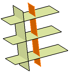
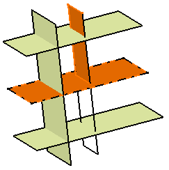
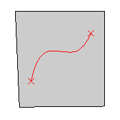
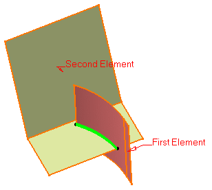
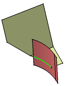
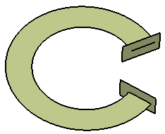
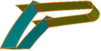
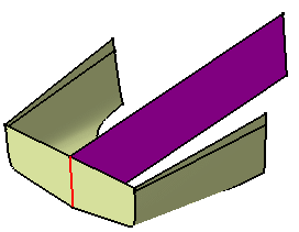
You can split a wireframe element by a point, another wireframe element or a surface; or a surface by a wireframe element or another surface.
Open the Split1.CATPart document.
-
Click Split
 .
.The Split Definition dialog box appears. 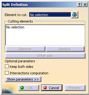
-
Select the element to be split.
-
Select the cutting element.
-
Click OK to split the element.
The created element (identified as Split.xxx) is added to the specification tree. In the case several elements to cut were used, the created elements are aggregated under a Multi-Output.xxx feature. 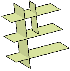
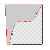
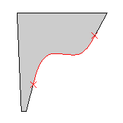
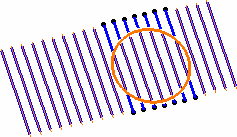
In the illustrations below, the top-left line is the first splitting element. In the left illustration it defines an area that intersects with the other three splitting curves, and in the illustration to the right, these three elements are useless to split the area defined by the first splitting element. 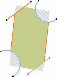
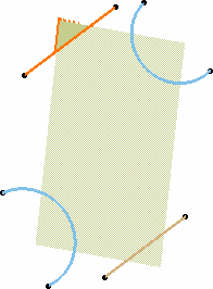
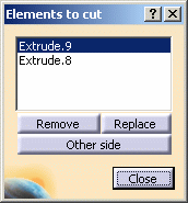
Would you need to remove or replace one of these cutting elements, select it from the list and click Remove or Replace .
Keeping or Removing Elements
- Click Show parameters >>.
- Click in the field of your choice to be able to select the elements in the 3D geometry.
- Right-click in the field either to clear the selection or display the
list of selected elements.
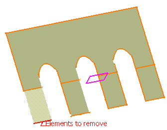
Only the selected element is removed.
All other elements are kept
The selected elements are kept.
All other elements are removed- You must select sub-elements as elements to keep or to remove;
otherwise, a warning message is issued.
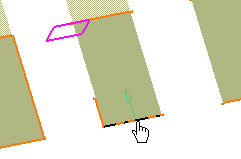
- You can also select a point to define
the portion to keep or to remove.
A contextual menu is available on the Elements to remove and Elements to keep fields. 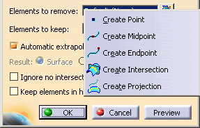
- You do not need to select elements to keep if you already selected elements to remove and vice-versa.
- Select Keep both sides to retain the other side of
the split element after the operation. In that case it appears as
aggregated under the first element.
Therefore both split elements can only be edited together and the aggregated element alone cannot be deleted. If you use the Datum mode, the second split element is not aggregated under the first one, but two datum surfaces are created.
- Avoid splitting geometry when the intersection between the element to cut and the cutting element is merged with an edge of the element to cut. We advise you to use the Elements to remove and Elements to keep options to remove the positioning ambiguity.
- In case there are several elements to cut, Keep/Remove and Keep both sides only apply on the first selected element.
- In case the intersection between the elements is not connex, an error message may be issued prompting you to choose the elements to be kept or not.
-
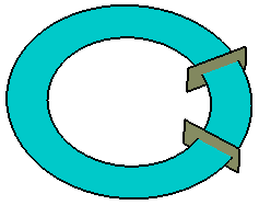
Select
the
Ignore no intersecting elements check box to split many elements
(curves, surfaces, volumes)
when the cutting element does not intersect all the elements.

When this option is selected, the Intersections computation option is cleared and grayed out. -
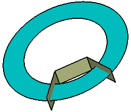
Select
the
Keep
elements in half space check box to keep all the elements that
are on one side of the cutting infinite plane.
The cutting element defines this half space.

- This option applies only when the cutting element is an infinite plane.
- If the split side is not towards the element to cut, an error message is issued. Note that, this behavior differs from the behavior in the Part Design workbench, i.e. no error message is issued.

When this option is selected, the Ignore no intersecting elements option is automatically selected and grayed out.

Elements to cut: dark blue and light blue surfaces
Cutting elements: yellow and purple planes
Result with Ignore no intersecting elements selected

Element to cut: non connex light blue surface
Cutting element: yellow plane
Result with Keep elements in half space selected
- You must select sub-elements as elements to keep or to remove;
otherwise, a warning message is issued.
Intersecting and extrapolating
- Select Intersections computation to create an aggregated
intersection when performing the splitting operation. This element will
be added to the specification tree as Intersect.xxx.
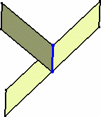

In case there are several elements to cut, the Intersections computation option only applies on the first selected element.
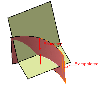
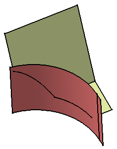
- Clear Automatic extrapolation if do
not you want the automatic extrapolation of the cutting curve.
When a splitting curve is extrapolated, the extrapolation will be performed on the original curve, providing the underlying geometry (that is the curve) is long enough to be used for the extrapolation. If Automatic extrapolation is deselected, an error message is issued when the cutting element needs to be extrapolated, and the latter is highlighted in red in the 3D geometry. 
This option is available in the case of a split surface/curve or surface/surface. 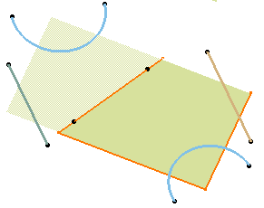
Splitting Wires
- When splitting a wire (curve, line, sketch and so forth) by another
wire, you can select a support to define the area that will be kept after
splitting the element. It is defined by the vectorial product of the
normal to the support and the tangent to the splitting element.
This is especially recommended when splitting a closed wire. The non disconnected elements of the element to cut are kept in the result of the split. 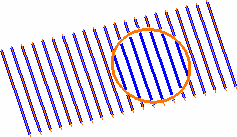
Splitting with no support selected, first solution Splitting with no support selected, second solution 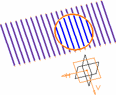
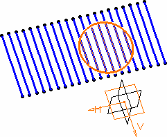
Splitting with a selected support (xy plane), first solution Splitting with a selected support (xy plane), second solution
