-
Click Thread Dimension
 in the Dimensioning toolbar (Dimensions
sub-toolbar).
The Tools Palette is displayed, to let you select the dimension representation.

-
Select the thread to be dimensioned in the front view.
In this case click on the thread diameter, and the dimension is created.
Depending on whether the thread has been automatically or manually created and/or standard has been specified in your 3D document, you will have following cases:Automatically created 3D Thread without a standard Automatically created 3D Thread with a standard Created 2D Thread with no association to 3D Thread -
The dimension is created from a 3D thread and this 3D thread has no standard.
-
The dimension is created from a 3D thread and this 3D thread has a standard.
-
The dimension is created from a 2D thread (no 3D thread is associated to this 2D thread) or from two parallel lines.
-
The value of the thread diameter dimension is the 3D thread diameter value and a diameter symbol is set as a prefix on the dimension. This prefix can be edited but cannot be deleted or replaced at dimension update.
-
The value of the thread diameter dimension is the description of the 3D thread (the prefix of the dimension cannot be defined).
-
The value of the thread dimension is the diameter of the 2D thread (top view) or the distance between the lines (side view) and a prefix M is added to the dimension value.
-
The thread diameter appears as:

-
The thread diameter appears as:

-
The thread diameter appears as:

Right-click the dimension and select Dimension1.object > Dimension Representation > Force Horizontal Dimension in View, the dimension appears as:

(or Force Vertical Dimension in View).

-
-
Click Thread Dimension
 again.
 -
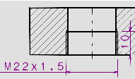
In the section view B-B, select one of the two lines representing the thread to be dimensioned.

Two thread dimensions appear, representing the thread diameter as well as the thread depth.


-
The dimensions are created as feature dimensions. If the Activate analysis display mode check box is selected in the Tools > Options > Mechanical Design > Drafting > Dimension tab, Analysis Display Mode area, these dimensions are displayed using the color defined for Technological feature dimensions in the Types and colors dialog box (click the Types and colors... button in the Analysis Display Mode area).
-
In the top view, you can modify the orientation of threads dimensions.
-
If the thread diameter dimension is created from a 3D thread and this 3D thread has a standard, the value of the dimension is the description of this 3D thread and the prefix of the dimension cannot be defined.

-
If the thread diameter dimension is created from a 3D thread and this 3D thread has a no standard, the value of the dimension is the 3D thread diameter value and a diameter symbol is set as a prefix on the dimension. In this case, this prefix can be edited.

-
If the 3D thread has a standard description, the value of the associated thread diameter dimension is always the Thread Description (Hole Definition dialog box, Thread Definition field) as of the 3D thread. The dimension value cannot display the diameter of the 3D thread in the side view as well as in the top view (except if you add a fake value).
-
Thread dimensions created on top views are technological features, so they cannot be re-routed.
-
Thread dimension on top view remains associative to 3D thread even though 2D thread is deleted.
Thread dimensions based on top views |
|
| Thread dimension properties based on top views can
be created either automatically or manually depending on
whether a thread dimension and/or a standard have been
specified in your 3D document. Refer to Creating
Threaded Holes to know more about specifying
threads in 3D holes.
The following table summarizes information about thread dimensions computing based on top views:
|
|||||||||||||||||||||||||||||||
|
|
If the Thread option is not selected in 3D, a 2D thread can be added manually. The thread dimension is not directly linked to 3D. |
Thread dimensions based on side views |
|
| Thread dimension properties based on side views can be
created either automatically or manually depending on
whether a thread dimension and/or a standard have been
specified in your 3D document. Refer to Creating
Threaded Holes to know more about specifying threads
in 3D holes.
The following table summarizes information about thread diameter dimensions computing based on side views:
|
|||||||||||||||||||||||||||||||
- In pre-R18 documents, during the creation of thread dimensions, NO_DESC_IN_DRAFTING AND DESC_IN_DRAFTING keys defined in 3D standards determined the dimension type created.
- There is no change in the behavior when updating pre-R18 thread dimensions.
- Thread depth dimensions behave as diameter dimensions. However, they have no prefix and their value is the thread depth value defined in 3D.
Threaded hole dimensions behavior with Standard specified |
|
|
Threaded hole dimensions behavior with No Standard specified |
|
|
![]()


