- OpenGL shader technology can be used with this functionality, please refer to the Infrastructure Installation Guide documentation for more details on software & hardware prerequisites: Software Requirements. See Performance setting.
- The different mapping analyses of the same surfaces cannot be displayed simultaneously, even if you have set the mapping analyzes in no show. You need to visualize them one after the other.
- The discretization option should be set to a maximum (in Infrastructure User's Guide, see Performance: the 3D Accuracy > Fixed option should be set to 0.01 and the Curves' accuracy ratio option should be set to 0.10s).
The Isophote Mapping Analysis dialog box is displayed.
The Isophote Mapping Analysis dialog box displays the following information:
-
Mapping Type:
-
Option:
-
 Global: lets you analyze the whole part. Deselect this icon to
make the analysis element by element.
 -
 Compass:
flips the compass to the model and lets you move the compass in the 3D
geometry to define the orientation. This option is selected by default.
 -
 Show/hide the manipulator: shows or hides the
manipulator.
 -
 View:
lets you use the screen definition to define the analysis point of
view. Stripes are recalculated each time you move the screen point of
view. This option is selected by default.
 -
 Eye:
lets you use the User Eye manipulator location to define the
analysis point of view. Stripes are recalculated each time you move the
User Eye.
 -
 Point:
defines the mapping analysis directions from the current analysis point
of view.
 -
 Light Sources On/Off: sets the display option of light sources
as "off/on".
 -
 Highlight On/Off effect: sets the display option of
highlight effect
sources as "on/off". When checked "On" the surfaces are
selected but they will not be seen in the specification tree.
 -
 Plane:
defines the mapping analysis directions are normal to the plane
representing the point of view. This option is not available with the
Eye option.
-
-
Zebra parameters:
-
Number of stripes: sets the number of stripes.
-
Width of stripes: sets the width of stripes.
-
Color transition: sets the zebra color transition.
-
-
Radius: defines the cylinder or sphere radius, by default 1000mm.
-
Select Sphere.1
The analysis results depend of the current object. May you want to change the scope of analysis, use the Define in Work object contextual command.
-
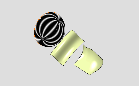
Select the Cylindrical mode mapping type:

Isophotes are applied on Sphere.1.
-
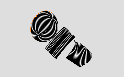
Select the Global option:

Isophotes are displayed on all the part. It is advised to use the Global mode for a global selection rather than using a trap.
-
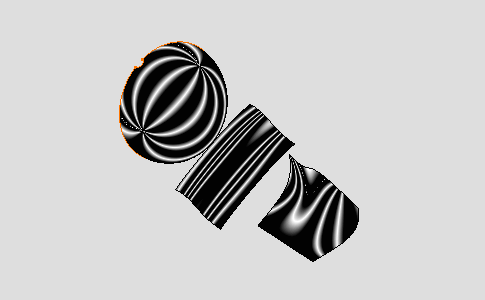
Select the Plane option:

The mapping analysis directions are normal to the screen plane. Compare with the image above where the mapping analysis directions are defined from the center of the screen plane.
-
Select the Compass option:

-
This option flips the compass to the model and lets you move the compass in the 3D geometry to define the orientation of the current mapping.
-
The cylindrical mapping appears.
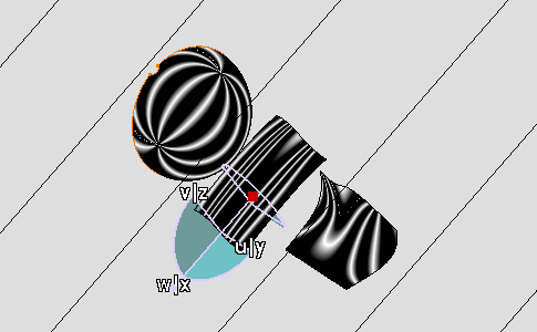
-
Manipulate the compass to modify the isophotes orientation.
Isophotes mapping is modified accordingly to the isophotes orientation.
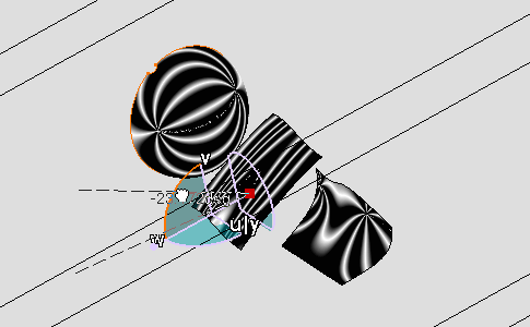
-
Manipulate the view orientation with the mouse modify the isophotes and surfaces orientation.
Isophotes mapping is modified accordingly to the new point of view.
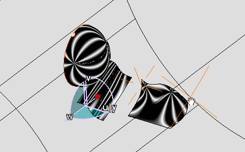
-
Select the Eye option:
 , note that the
Point option
 is automatically
selected.
-
The Eye User manipulator appears and it allows you to define another point of view independently from the screen point of view.
-
You can move the Eye User along its axis or by selecting its center: isophotes mapping is modified accordingly to the Eye User orientation.
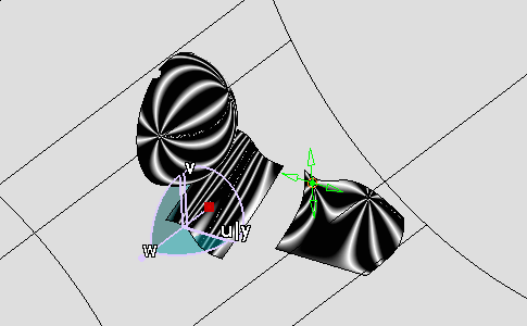
-
Right-click the Eye User .
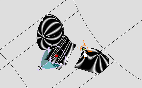
A contextual menu is displayed:

-
Edit: this command allows you to define the Eye User manipulator parameters.
-
Keep this point: this command allows you to create the point where you clicked.
-
Select Edit from the contextual menu.
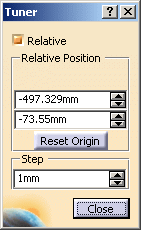
The Tuner dialog box appears:
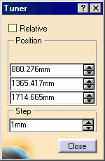
In this dialog box you can set:
-
Relative: defines whether the Eye User location is defined according to the relative origin.
-
Position: defines the Eye User location coordinates according to the Relative option cleared:
-
X: defines the X coordinates.
-
Y: defines the Y coordinates.
-
Z: defines the Z coordinates.
-
-
Step: defines the step when you move the Eye User.
-
Select Relative option in the Tuner dialog box.
The relative origin of the Eye User is displayed.
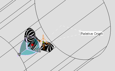
The Tuner dialog box is modified:
In this dialog box you can set:
-
Relative Position: defines the Eye User location coordinates according to the Relative option selected:
-
Y: defines the relative Y coordinates.
-
Z: defines the relative Z coordinates.
-
Reset Origin: reset the origin at the current Eye User location point.
-
-
Click Close in the Tuner dialog box.
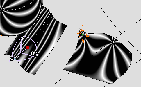
-
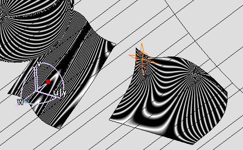
Increase the number of stripes using sliders
Number of stripes increases, the cylindrical mapping is modified accordingly:
-
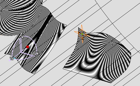
Decrease the width of stripes using sliders
Width of stripes is modified.
-
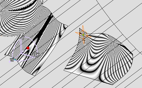
Increase the Color transition using sliders
Color transition is modified.
-
Click OK when you have finished the analysis.
The analysis (identified as Isophotes Mapping Analysis.x) is added to the specification tree under the Free Form Analysis node.

