CFO or FMP or (FR1 and TG1 and HA1) applications are required to access the Wall Thickness Analysis capability.
In case you do not have any of them installed, you can nevertheless edit all analysis parameters (except for the body to analyze) or update already stored wall thickness analyses.
-
Click Wall Thickness Analysis
 in the
Analysis toolbar.
in the
Analysis toolbar.
The Wall Thickness Analysis dialog box is displayed.
-
Select the body of interest.
The selected body is then set as the current object.
-
Keep Sphere as the computation method. The other method available is Ray. For details, see About Analyzing Wall Thickness Analysis.
-
Keep Tolerance as the parameter defining the calculation precision you want. The other possible parameters are tesselation parameters: Sag and Step.
-
Enter the value to define the tolerance you want. In this example, enter 0.4mm. The analysis result will therefore fall within the specified tolerance value. For details, see About Analyzing Wall Thickness Analysis.
-
Select the Colors tab to access ranges of colors for your display.
-
Autoscale provides dynamic range scaling for thicknesses.
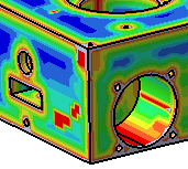
By default, the number of values to be used to calculate different ranges is 10. For the purpose of our scenario, keep this value. Setting 10 values lets the system compute 11 ranges of thicknesses. A color is assigned to each range by the system.
The bright red color identifies the thinnest areas of the part, that is areas comprised between 0mm and 10mm.
-
Click Run to launch the analysis.
The measure is performed over the whole selected body. A window appears, informing you about the operation progress. In case you want to interrupt the operation, just click Cancel.
When the computation is done, the colors assigned to the different value thickness show the thickness variation of the part, so that you can immediately observe critical areas where the thickness is not appropriate.
The part looks like this:
-
In case you are interested in only a few thicknesses and therefore prefer to ignore some areas of the part, just clear the color you do not want to display on the part.


-
For the purpose of our scenario, select all colors again.
-
Select the Options tab to access display options.
By default, On the fly is selected. This option lets you know the thickness value at the point where you position your cursor on the part. The value is displayed in mm, and is not persistent.
- When On the fly is selected, you can select Display sphere which shows the sphere under the cursor. Its diameter is equal to the analysis value on the point.
- When On the fly is selected, you can make the thickness value displayed permanent by right-clicking and selecting Fix indicator.
-
In the Inputs tab, Method list when you choose Sphere as a computation mode, No sharp edge option is available in the Options tab, Graphics field. This option filters out the areas close to edges and which thickness is less than the value set in the corresponding value field. Let us look closely at an example. If you keep the default value, that is 1mm, we obtain this display:

-
Change the value to 4.3mm and look at the updated display:
-


-

-
-

-
- Double-clicking on a color displays a palette from which you can set the color of your choice.
- The analysis will fail if the analyzed part is non-manifold or if it does not contain any volume at all.