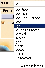
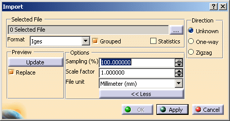
as well as information about the parameters specific to each format, if any:
- Ascii free
- Ascii RGB
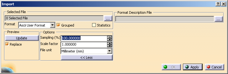
- Ascii User Format
- Atos
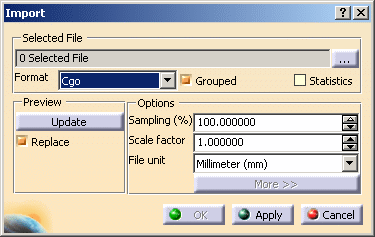
- Cgo
- Gom-3d
- Hyscan
- Iges
- Kreon
- Opton
- Steinbichler
- Stl
- 3DXml (tessellated).
Parameters common to all formats are described in Importing One Digit File or Importing Several Digit Files.
Available Formats
In Digitized Shape Editor
In STL Rapid Prototyping
- In Cgo, Ascii free and IGES
formats, you can not process more than 10,000 points at each import,
in one or several files, e.g. you can not import 4 files of 3,000 points each in one shot but you can import them separately. - This limitation applies to the input files (before Sampling or resizing with the bounding box).
- If you try to import over 10,000 points in one shot, a fatal
error panel is displayed:
Too many points for this configuration.- If the Grouped option is active, no file is imported.
- If the Grouped option is not active, files are
imported as long as the sum of their points does
not exceed 10,000 points.
- Mesh Regeneration is not available on those files.
In Shape Sculptor
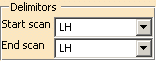
Ascii free

Perceptron (ascii) files can be imported by selecting the Ascii free format and
setting the
Delimitors for Start scan and End scan to
LH (do not forget a blank before
LH).
Ascii RGB
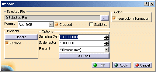
Keep color information is selected by default, and lets you keep the color information found in the Ascii RGB file, if any.
Ascii User Format
Additional information attached to the points, such as point symbol or color, are imported and taken into account as point properties.
Please note that:
- To enable this import, you must describe the User Format in a .FDF file (Format Description File) and enter the path of this file in the dialog box.
- If the Format Description File is not found, invalid or if the input file does not correspond to the format described, import operation fails and a specific error message is displayed
- All user information are imported but not all of them have an influence.
- If the format contains more than once text attribute, all texts are displayed under the mouse cursor (one text per line).
- The input file cannot not contain redundant or conflicting information (2 different color attributes for instance).
- If the input file contains a specific property not described in the format file, this property is ignored at best or an error message is displayed and import fails.
- There is no user mapping table management. For example, a point symbol attribute can only have one of V5 standard symbols value.
- If the point description does not have a specific property, the point is displayed with the standard default representation.
Depending on their type, some imported point information can be taken into account in the cloud of points display:
- Color attribute: select the Colored check box in the Display Modes tab of the properties of the import result to use the information from the digit file. Otherwise, the current display is applied.
- Display symbol: select the Symbol check box in the Display Modes tab of the properties of the import result to use the information from the digit file. Otherwise, the current display is applied.
- Information text (displayed under the cursor when the mouse hovers
over a point). Select the Dynamic display of information check
box in the Tools>Options>Shape>Digitized Shape Editor>Display Modes
tab to display information from the digit file.
Format Description File
This file is a simple one line ASCII text file.
The format is described by a set of keywords separated by a space.
Each keyword indicates the type of expected data.
Note that:
- Keywords can be defined in any order. However, the digit file must respect the order in which you have defined the keywords.
- The format must be described on a single line in the file.
- Only the X, Y & Z information is required in the format. Other keywords are optional.
- RGB color & Color Index information cannot be used simultaneously in the format.
- You can define more than one TEXT information in the format.
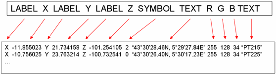
Available keywords are defined in the following table:
| Keyword | Type | Definition | Value | Mapping | Comment |
| X | double | X coordinate of the point | |||
| Y | double | Y coordinate of the point | |||
| Z | double | Z coordinate of the point | |||
| DX | double | ||||
| DY | double | ||||
| DZ | double | ||||
| R | integer | Red component of point color | [0..255] | Must be associated with G and B | |
| G | integer | Green component of point color | [0..255] | Must be associated with R and B | |
| B | integer | Blue component of point color | [0..255] | Must be associated with R and G | |
| A | integer | Alpha component of point color | [0..255] | ||
| COLOR | integer | Color index in the color table | 0 | BLACK | |
| 1 | WHITE | ||||
| 2 | RED | ||||
| 3 | GREEN | Default value | |||
| 4 | BLUE | ||||
| 5 | YELLOW | ||||
| 6 | MAGENTA | ||||
| 7 | CYAN | ||||
| SYMBOL | integer | Marker used for point display | 0 | SMALL_DOT | Default value |
| 1 | DOT | ||||
| 2 | STAR | ||||
| 3 | FILLED_SQUARE | ||||
| 4 | FILLED_CIRCLE | ||||
| 5 | CONCENTRIC | ||||
| 6 | CIRCLE | ||||
| 7 | PLUS | ||||
| 8 | CROSS | ||||
| LABEL | string | Such a text is just for file readibility. It is not imported in V5. |
The text does not contain space character | ||
| TEXT | string | Free text | The text must be enclosed in double-quotes | ||
| USELESS_INFO | Useless information. It is not imported in V5. |
Example of a Format Description File:
File of points
Please note that:
- The file format must be consistent with the Format Description File,
- Only one point definition per line is accepted,
- Available data separators are SPACE or TAB characters,
- Starting a line with exclamation mark ("!") indicates that it is a line of comment. The content of such a line is not taken into account,
- Decimal notations with DOT or COMMA or xx.xxxe+xx are supported
Atos
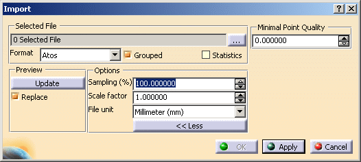
Minimal Point Quality
is used to clean
the file from invalid points.
The quality value of a point lies between 0 and 255 (low to high).
Choose a value to ignore points below that value:
-
Minimal Point Quality value is 125:
-
Minimal Point Quality value is 75:

Cgo
Gom-3d
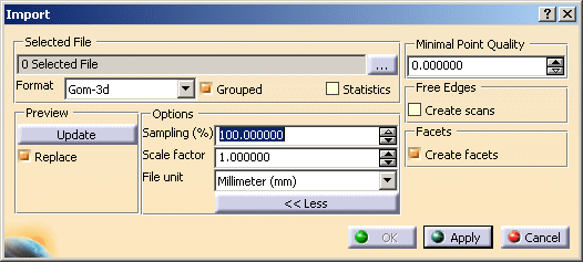
Files are imported as as points, scans, grids or meshes.
Minimal Point Quality
is used to clean
the file from invalid points.
The quality value of a point lies between 0 and 255 (low to high).
Choose a value to ignore points below that value:
-
Minimal Point Quality value is 125:
-
Minimal Point Quality value is 75:
Free Edges is used to create or not the
scans representing the free edges of a mesh:
 or
or
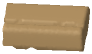
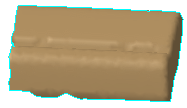
Facets is used to create or not the facets of the imported mesh:
 or
or

Hyscan

IGES
IGES Entities 116 are processed.
If the cloud to import is made of Entities 116 only, the result is a
cloud of points.
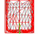
Otherwise, the result is made of scans.
Direction applies to scans. Select the required option whenever you know it.
Kreon

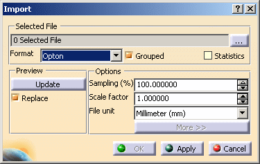
Opton
Steinbichler
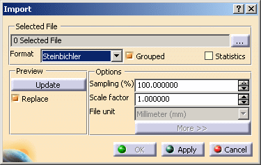
Files are imported as points, grids or scans.
STL
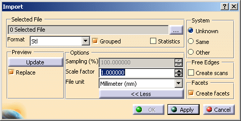
Both bin or ascii STL formats are supported.
System applies to the operating system (Unix or Windows NT) used to generate the binary data. Select :
- Same if you know you are using the same operating system as the one used to generate the binary data,
- Other for the other way,
- Unknown if you have no indication.
Free Edges is used to create or not the
scans representing the free edges of a mesh:
or
Facets is used to create or not the facets of the imported mesh:
or
3DXml (tessellated)
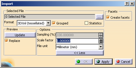
Facets is used to create or not the facets of the imported mesh:
or