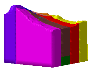
The drawing can be created in two View generation mode:
- Approximate,
- Exact view:
- Reliability and performance are better than in approximate mode,
- You can draw sections along polylines, these polylines being either interactively drawn or stored in a sketch.
- Construction elements can be included.
- You must have access to the Drafting workbench.
- Go to Tool > Options > Drafting > Administration and select the Prevent generative view style usage check-box if you do not want to use generative view styles when creating or updating views. Otherwise, clear this check box.
- In the Administration Tasks, you will find information about the GVS parameters for Clouds and ZLevel Maps (if required).
- The generative view styles mechanism is described in the Generative Drafting User's Guide.
- The meshes must all be under Geometrical Sets or Ordered
Geometrical Sets. However, it is not mandatory to have them all under one
single Geometrical Set or one single Ordered Geometrical Set.
Meshes under a Hybrid Body or a Body in a Set are not taken into account. - All meshes must be displayed in Smooth mode, not in Flat mode.
- Hide all the elements and sets that you do not want to transfer into the drawing.
Approximate
-
Go to Tools > Options > Mechanical Design > Drafting and select the View tab. Make sure that View generation mode is set to Approximate.
-
In the Drafting workbench:
- click the drawing window to activate it,
- select Front View
 .
.
In the CATPart containing the meshes, select xy plane.
-
On the sheet, a blue knob appears, as well as a green frame containing a preview of the view to be created.
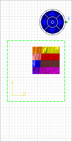
The knob lets you define the location and orientation of the view to be created, using the blue manipulators: top, bottom, left, right or rotated according to a given snapping, or according to a specified rotation angle. Click the drawing sheet or at the center of the blue knob to generate the view:
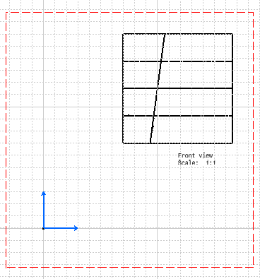
-
Generate a section cut of the meshes:
- In Drafting, select Insert > Views > Sections > Aligned
Section Cut
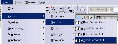
- and select Sketch.4 in the MeshDrafting01.CATPart window. The
sketch is added to the drawing and a preview of the Aligned Section
Cut is displayed:

- Indicate the location of the Aligned Section Cut by a
pick in the drawing:

- In Drafting, select Insert > Views > Sections > Aligned
Section Cut
-
Generate a section view of the meshes:
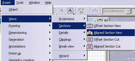
- Proceed as in step 3., but select Insert > Views > Sections > Aligned
Section View:

- All these views are on one sheet:
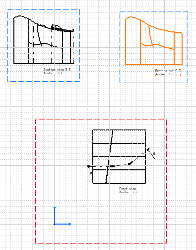
- Note that graduations are not generated automatically, even in section cuts.
- Proceed as in step 3., but select Insert > Views > Sections > Aligned
Section View:
-
You can add names and geological symbols of each layer.
As they are not generated automatically, you must create them manually.
Geological Layers with Construction
Constructions represented by
elements other than meshes can be taken into account:


or

![]()