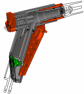
3D section cuts cut away the material from the plane, beyond the slice or outside the box to expose the cavity within the product.
![]()
This task explains how to create 3D section cuts:
![]()
Insert the following cgr files: ATOMIZER.cgr, BODY1.cgr, BODY2.cgr, LOCK.cgr, NOZZLE1.cgr, NOZZLE2.cgr, REGULATION_COMMAND.cgr, REGULATOR.cgr, TRIGGER.cgr and VALVE.cgr.
They are to be found in the online documentation filetree
in the common functionalities sample folder cfysm/samples.
![]()
Creating 3D Section Cuts
-
Select Insert > Sectioning from the menu bar, or click Sectioning
 in the DMU Space Analysis toolbar and
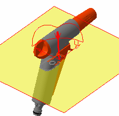
create a section plane. The
Sectioning Definition dialog box appears.
-
In the Definition tab, click Volume Cut
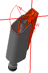
 to obtain a section cut:
The material in the negative direction along the normal vector of the plane (W-axis) is cut away exposing the cavity within the product.
Notes:
-
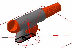
To give you the best view of the cut, the normal vector of the plane (W-axis) is inverted so that the cutting view is always visible on screen.
-
Partial clipping is not possible. Therefore if you select only one product in the Sectioning Definition dialog box, and click Volume Cut
 to obtain a section cut:
-
In the document window the visual feedback shows a section cut that affects the entire product structure even if you have selected only one product.
-
In the Section viewer, the section cut only shows the selected product.
-
-
Sketches and lines are not cut by the clipping render.
-
-
Double-click the normal vector of the plane to invert it, or click Invert Normal
 in the Positioning tab of the Sectioning Definition
dialog box.
-
Re-click Invert Normal
 to restore the material cut away.
 -
Click OK when done.
3D Section Cut Display
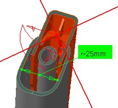
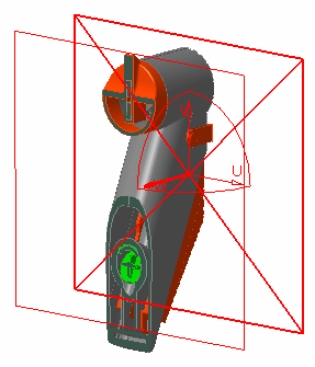
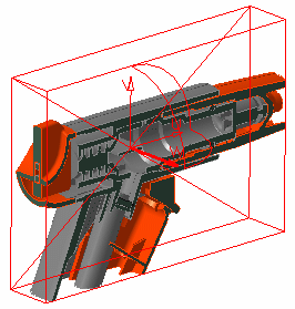
The 3D section cut display is different when the sectioning tool is a plane. To obtain the same display as for slices and boxes (see illustrations below) and make measures on the generated wireframe cut:
-
Select the Allow measures on a section created with a simple plane option in the DMU Sectioning tab (Tools > Options, Digital Mockup > DMU Space Analysis)
-
Then, create your section cut based on a plane.
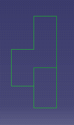
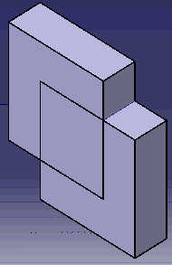
When the Sectioning Tool is a Slice:
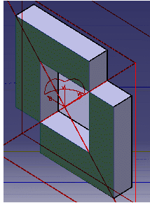
When the Sectioning Tool is a Box:
|
|
Sectioning filling capability in case of special cases:In case of special scenario of section curve
with volume cut, the sectioning command will not be able
to recognize the resulting contour as a closed contour. Hence the
section result will not be filled in section 3D & 2D Viewer.
However, with option ‘Allow
measures on a section created with a simple plane’
activated, the result will be:
|
Hiding 3D Section Cuts
Hiding 3D Section Cuts will remove the clipping from the 3D Viewer as well as the section wireframe. The selection or un-selection of the option "Allow measures on a section created with a simple plan" does not have any impact on this behavior.
P2
Functionality
In DMU-P2, you can turn up to six independent section planes into clipping planes using the Volume Cut command to focus on the part of the product that interests you most.
|
|
3D Section Cuts in DMU Review
Section cuts created during DMU Reviews are not persistent and are only valid for the duration of the review. If you exit the DMU Review, the section cut is lost.
|
|
For more information about DMU Review, refer to DMU Navigator User's Guide |
![]()
