Profile bending transforms straight profiles into formed shapes, and is typically used for stiffeners along the hull shell.
In most shipyards, profile bending marks inverse bending traces or curves on the web of the profile, and in some cases, requires profile bending templates. Both inverse bending traces and templates assist in forming the desired shape. This operation is typically done by profile-bending machines.
To detail a profile bending operation you can do the following:
-
Open the CATProcess containing the Shell.CATProduct.
-
Identify the shapes along the shell in the Product List.
-
Select Profile Bending Operation
 .
. -
Select BottShell_TStf_009.11 in the ProductList of the PPR tree.
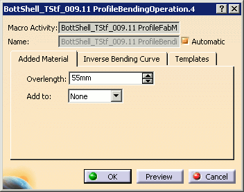
The Profile Bending Operation dialog box appears:
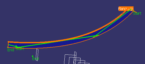
Inverse bending curves are previewed in the geometry area:
-
Define the amount of stock to add to the shape before cutting and bending in the Overlength box, and specify to which end or ends of the shape in the Add to list.
You can apply stock to both ends, one end or no end.
Note: Start and End are indicated in the geometry area to help you identify shape ends. -
Select the Inverse Bending Curve tab.
-
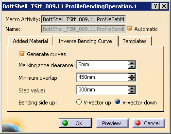
Specify whether or not you want to generate inverse bending curves.
By default, these curves are generated. Leave this check box selected.
Note: Inverse bending curves can be generated automatically when building the operation list (see Tools > Options > Digital Process for Manufacturing > DPM - Structure Lofting or DPM - Structure Manufacturing Preparation > Activities). -
Enter values for the marking zone clearance, minimum overlap and step value, and identify the bending side up.
Marking zone clearance: specifies a clearance zone in which inverse bending curves will not be generated. 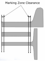
Minimum overlap: specifies the minimum distance between the ends of inverse bending curves. 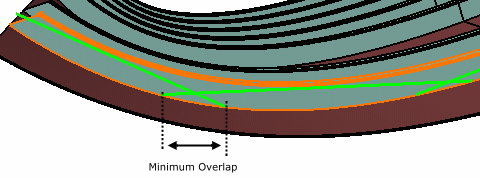
Step value: defines the work lines spaced along the neutral axis that are used to extract inverse bending curve data. This is an attribute on the inverse bending curve item. Bending side up: identifies the side to mark. The side is determined with respect to the local u- and v-axes of the shape cross-section. The v-vector orients the local v-axis. 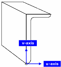
-
Select the Templates tab.
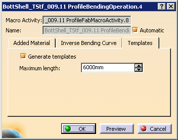
-
Specify whether or not you want to generate templates.
By default, templates are generated. Leave this check box selected. -
Enter the maximum length for the template.
This value is used to determine whether to generate more than one template. If the length along the neutral axis is greater than the maximum length entered, more than one template is generated. -
Click OK when done.
Inverse bending curves are created on the profile web as defined in the dialog box. Any overlength specified is also created.

Templates are resources and are stored in a CATPart under the ResourcesList node in the PPR tree, with one body per template. This body contains the projected web surface with any openings and endcuts. Templates are also identified under the Resources node of the appropriate operation. 
-
Re-edit the operation to visualize the projected web surface in the geometry area.
Note: You may need to rotate the sample to visualize the surface. -
Open the template under the Resources node in a new window.
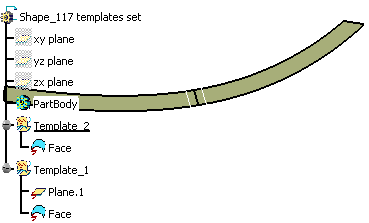
In the example below, two templates have been generated for this shape: the length along the neutral axis was greater than the maximum length of 6000mm entered in the Profile Bending Operation dialog box.
-
Close the window.
-
Update the in-process model (using the IPM Update command).
-
View the IPM part:
Note that the IPM part contains all the necessary features for the downstream bending operation: inverse bending curves and any stock or overlength specified.
-
Edit the profile bending operation and change inverse bending curve specifications, then update the in-process model and view the IPM part again.
![]()