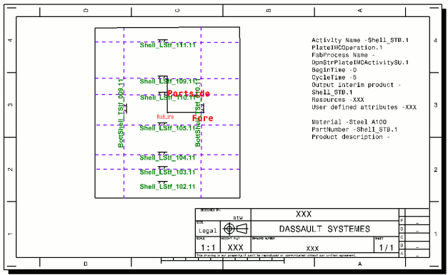
- Fabrication sketches. A fabrication sketch is a CATDrawing
file representing the sketch of a part (flat or curved plate, straight,
bent or rolled profile) ready for manufacturing and is used as input for
marking and cutting operations. It contains dimensions, annotations and
some identification data.
For curved plates, the fabrication sketch is also used for forming operations and shows, in addition, roll lines, template location lines and reference lines.
Note: The system automatically detects whether the plate is flat or curved and generates the CATDrawing with the appropriate data.
For profiles, the fabrication sketch is a not-to-scale CATDrawing and shows two views of the profile. - Nesting data. This data is contained in a DXF file.
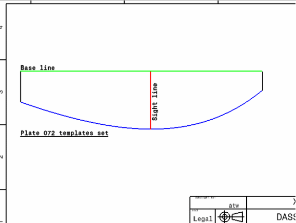
- Template sketches for plates and shapes. A template sketch is a CATDrawing file with a number of sheets, each sheet representing the shape of one template. In addition for plates, it contains the base plane trace, the template curve, the sight plane trace and annotations.
- Not-to-scale profile drawings. A CATDrawing showing a symbolic view of the straight profile.
- Inverse bending curve data. This data is contained in an XML file.
CATDrawings can then, if desired, be edited using the V5 Drafting workbench, for which the appropriate license is required.
The Structure tab in the Properties dialog box lists all workshop documents associated with the selected activity.

Plate Fabrication Sketch
Corresponding DXF File
This example shows a portion of the corresponding DXF file. There is no title block nor frame and the scale is set 1:1.
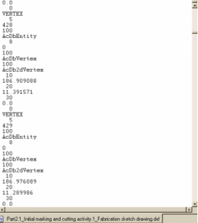
Plate Template Sketch
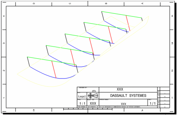
The 3D model showing five plate forming template resources:
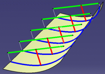
The extracted workshop document is based on the drawing template which contains one sheet with the frame and title block.
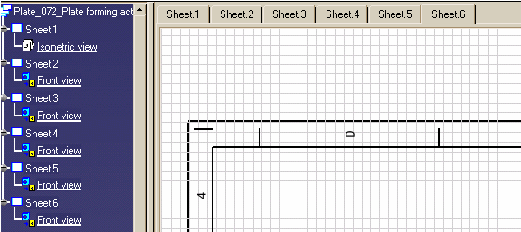
Plus a first sheet showing the isometric view of templates on the curved plate. This sheet has the same viewpoint as the 3D model. If the user changes the viewpoint, for example, rotates the model, then generates the drawing again, the isometric view on the first sheet will be updated to reflect the viewpoint of the 3D model.
Profile Template Sketch
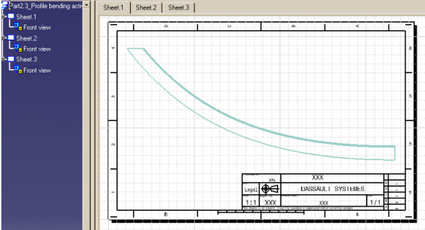
The composition of the CATDrawing is very similar to that for the plate template sketch. The only difference being that the first sheet contains a front view of the curved profile as shown below.
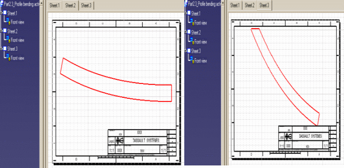
Inverse Bending Curve Data
The in-process model of the straight profile:
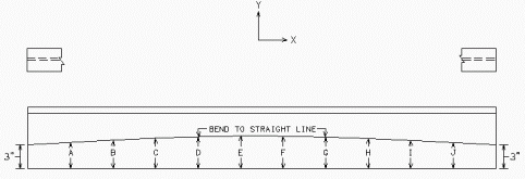
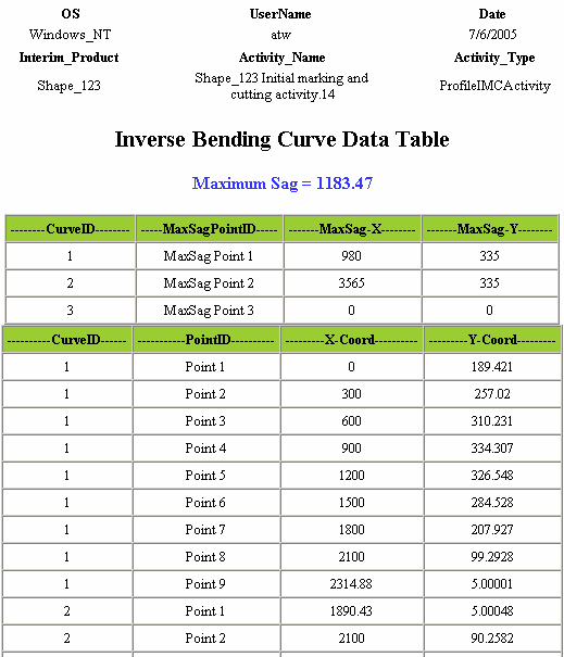
This table will also contain maximum sag point information.

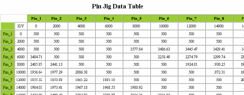
An XSL stylesheet is necessary to show data in tabular form. This stylesheet is located in the same place as the XML file itself. You will be able to replace this XSL stylesheet with another or with a CSS stylesheet to have data formatted as per your practice.
Pin Jig XML Data File
Here is an extract from a typical pin jig XML data file:

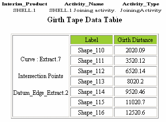
Girth Table XML Data File
Here is an extract from a typical girth table XML data file:
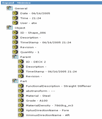
Profile XML Data File
Here is an example of a Profile XML data file.
Pin Jig Resource Drawing
This typical Pin Jig resource drawing shows the top view of panel
profiles placed on the pin jigs workshop. Cross marks show the position of
each pin on the plates.
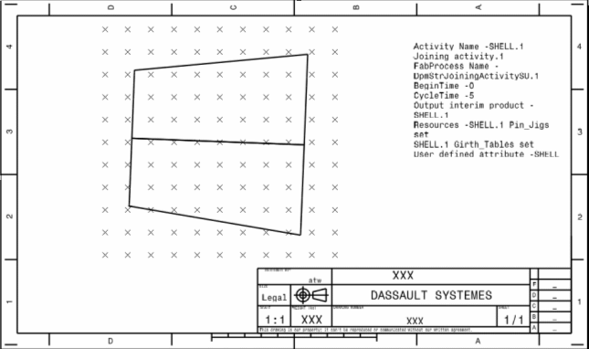
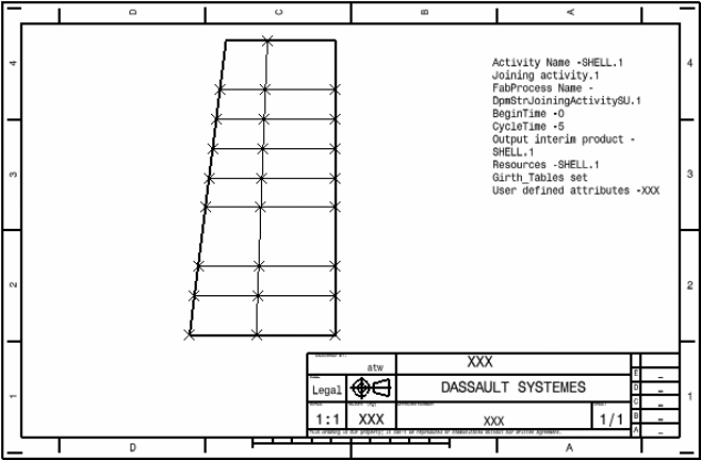
Girth Table Resource Drawing
This typical Girth Table resource drawing shows girth tapes laid on
plates and all the girth points with datum points.
