Important: You must have already generated the in-process model (IPM). Otherwise, you will not be able to extract fabrication sketches and a warning message will be issued.
Extracting a Plate drawing
-
Click Workshop Documents Extraction
 .
.The Workshop Documents Extraction dialog box appears. 
-
In the PPR tree, select the initial marking and cutting activity of each of the shell plates for which you want to generate a fabrication sketch.
Selected activities are listed in the top half of the dialog box. 
Notes:
- You can also select a process. If you do so, all child activities are listed in the top half of the dialog box.
- The Extraction Status column gives the status of already generated documents for the associated activity in the format x/y, where x is the number of documents extracted and y is the total number of documents.
- You can filter activities in the list by type using the Activity type filter drop-down list. All selects all lines in the list.
- Workshop documents of activities listed in the top half of the dialog box only can be extracted. For example, if you filter the list by Plate IMC, workshop documents related to plate IMC activities only can be generated.

-
Click Select All to select both activities and determine associated workshop documents.
Associated workshop documents are listed in the bottom half of the dialog box. An activity thus drives the list of extractable documents. 
Smart naming of workshop documents (
OutputProductName_RelatedProcess_WorkshopDocumentType) ensures easier identification of documents and enables simple database queries.The Already Extracted column (Yes/No) identifies whether or not the associated workshop document has already been generated.
-
Click the existing value in the To Extract column to indicate whether or not you want to extract the associated document. (Clicking this column switches the value from Yes to No and vice-versa.) Set To Extract to Yes for both workshop documents.
-
Select a location in which to save the documents.
By default, the documents are saved in a pre-defined location. Depending on your license, the location is either: - set on the Manufacturing Hub as the value of product_cadpath. The location you provide in the storage location field uses the product_cadpath location as its root.
- set in PRM XML
To browse for a location, click the button. The objects saved in the location depend on those listed with Yes in the To Extract column. You can sort the objects by Name or Type by clicking on the column headings.

-
Click Launch when done.
The drawings are generated and saved in the location identified in the Project Resource Management (PRM) file (by default, workshop documents are saved in C:\temp, see Managing Project Resources).An information box appears summarizing the process and indicating how successful or not it has been.
-
Click Yes to see traces and No to exit.
If you click Yes, the Fabrication Sketch Extraction Traces dialog box appears. 
Click Close to exit this dialog box.
-
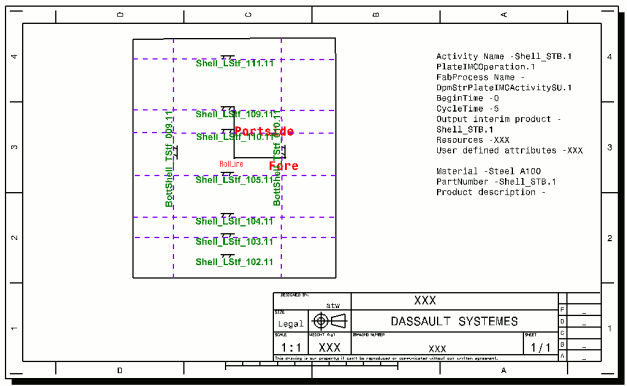
Open the CATDrawing generated using File > Open.

Note: The CATDrawing has a frame and title block (taken from the template drawing). The ship orientation and the name of the plate are also given.
Note: If text in a generated Workshop Document is too large for a particular part and appears to overlap, the font size of the text can be changed in the catalog according to the part in the GVS customization settings.
Extracting a Plate DXF file
-
Click Workshop Documents Extraction
 .
.The Workshop Documents Extraction dialog box appears. 
-
In the PPR tree, select the initial marking and cutting activity of each of the shell plates for which you want to generate a DXF file.
Selected activities are listed in the top half of the dialog box. 
-
Click Select All to determine associated workshop documents.
Associated workshop documents are listed in the bottom half of the dialog box. An activity thus drives the list of extractable documents. 
The Already Extracted column (Yes/No) identifies whether or not the associated workshop document has already been generated.
-
Ensure that the To Extract column is set to Yes for the DXF nesting data you wish to extract. If it is not, click the value in the To Extract column to change it to Yes. (Clicking this column switches the value from Yes to No and vice-versa.)
-
Click Launch when done.
The DXF file is generated and saved in the location identified in the Project Resource Management (PRM) file (by default, workshop documents are saved in C:\temp, see Managing Project Resources).An information box appears summarizing the process and indicating how successful or not it has been.
-
Click Yes if you wish to see traces, or No to exit.
-
Open the DXF file generated using File > Open.
