 |
In this task, you will learn
how to create a Functional Tolerancing and Annotation (FTA)
view. |
| |
Creating a Front View |
| |
The following task explains how to create front, section, or section cut
views/ annotation planes using the FTA workbench. These views are later
used to generate 2D views in the Generative Drafting workbench, during
2D extraction of the 3D part and annotations. |
 |
-
Open the CATPart document in the 3D FTA workbench.
-
In the Views/Annotation Planes
toolbar, click Front View
 . .
-
Select a face on the part.
The front view is created. It is represented by
a blue reference axis. 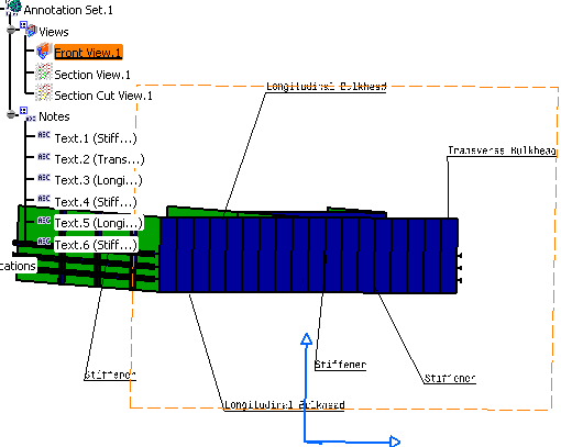
-
Similarly, create a Section View
using Section View/Annotation Plane  and a Section Cut View using a
Section Cut View/Annotation
Plane and a Section Cut View using a
Section Cut View/Annotation
Plane
 . For more information about creating views, see View/Annotation Planes in
3D Functional Tolerancing
and Annotation user's guide. . For more information about creating views, see View/Annotation Planes in
3D Functional Tolerancing
and Annotation user's guide.
-
Add annotations, as required. For
more information, see 3D Functional Tolerancing and
Annotation user's guide.
|
| |
Creating a View from 3D |
|
|
The following task explains how a 2D view is extracted from a 3D part
with 3D annotations. |
 |
You need to
apply the following settings:
- Go to Tools > Options > Mechanical Design > Drafting >
View tab. Make sure that Exact View is selected
as the View generation mode.
- Make sure that same standard is used in the CATDrawing and
CATPart documents. In this example, ISO is used as
the standard.
|
| |
-
Open the CATPart document, where you created the
Front, Section, and
Section Cut Views.
-
Create a new Drawing document. Tile the screen
horizontally by selecting Window > Tile Horizontally.
-
Click View From 3D  in the Views toolbar.
-
Select a view from the 3D or the specification tree.
A preview of the view is displayed in the Drawing.
-
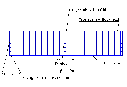
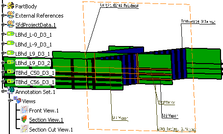
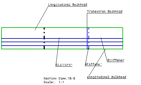
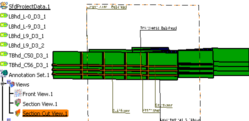
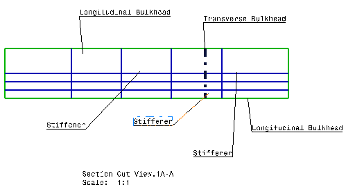
Click in the drawing document to generate the view. The images below
show the Front, Section,
and the Section Cut Views.
|
| |
2D Front View
|
 |
3D Section View
|
2D Section View
|
 |
 |
3D Section Cut View
|
2D Section Cut View
|
 |
 |
|


