ProfileType = This parameter is used to define the profile type (i.e. Tee, Pipe) and allows the user to apply the Create\Modify command of the Catalog Editor workbench to integrate his resolved sections in the catalog.
FamilyName = If the user uses the Create\Modify command, then ComponentFamily derives its name from this parameter, and this parameter in turns derives its name from the parametric CATPart name. For instance if the parametric CATPart name was AISC_Bulb_BigScale, the FamilyName parameter would be Bulb_BigScale and consequently the ComponentFamily name would be Bulb_BigScale.
CatalogName = This parameter derives its name from the parametric CATPart name and defines the standard. For instance if the parametric CATPart name was AISC_Bulb_BigScale, then the CatalogName parameter would be assigned to AISC.
PartNumber = This parameter derives its value from the PartNumber column defined in the design table.
SectionName = This parameter derives its value from the PartNumber column defined in the design table.
Required For Analysis Purposes:
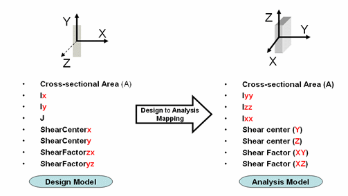
The list includes: Area (A), Principal Moment of Inertias (Ix, Iy,
and J), Shear Centers and Shear Factors. These parameters are also shown
in the left column of the following figure. Please note that the axis
definition in the design model is different from the one that will be
used in the analysis model. The existing mapping is illustrated below.

For more information on how to obtain these
section parameters, see Mesh Part properties under the Using Finite
Element Modeling User Guide.
For more information on Analysis section parameters, see the Generative
Structural Analysis User Guide.
General Nomenclature
D: Profile Height
Bf: Breadth of the Flange
Tf: Thickness of the Flange
Tw: Thickness of the Web
A: Cross-Sectional area
R(i): could be the Flange1Toe+Edge, Web Flange1Root + Edge,
WebFlange2Root + Edge, Flange2Toe+Edge... (i = 1, 2, 3, ...)
Slope: could be the angle between Flange2Inner + Edge and MoldedFlange2 +
Edge
Legacy parameters:
[Material]: -Not used- Was created systematically in any CATPart in
previous releases
[Code]: -Not used- Was mandatory for parametric design table in previous
releases