Modifying 3D Viewer Settings

This section contains the following information about Modifying 3D Viewer Settings.

About Modifying 3D Viewer Settings

When Modifying 3D Viewer  Settings

How to Modify 3D Viewer General Settings

How to Modify Units Settings

How to Modify Annotation Settings

How to Modify Measure Settings

How to Modify Section Settings

How to Modify Product List Settings

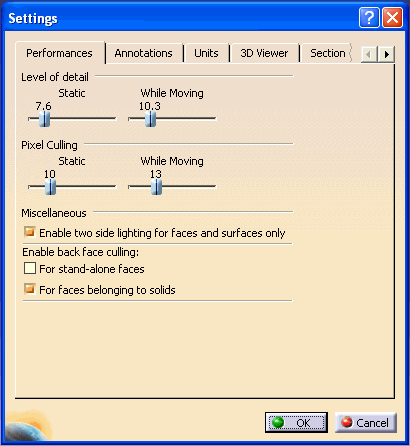
How to Modify Performance Settings

About Modifying 3D Viewer Settings

The ability to modify the 3D viewer settings provides you the opportunity to manage the visual display of a 3D model and the viewer performance in the following areas:

  • Color enhancement

  • Model view display

  • Measurement display

  • Grid properties

  • Product list editing

  • System performance and efficiencies

You can change the general settings of the viewer including background and model display. Annotation settings provide the user with the opportunity to modify the model line weights and style. Performance settings can be adjusted for performance or visual enhancement depending on your needs.

The unit settings can also be modified for calculation and measurement purposes.  Measure settings affect the display characteristics of the measurements and can be adjusted to your preference. You can change section settings, which affect the grid properties. Product Lists can also be included or modified in the model.

When Modifying 3D Viewer Settings

You can modify the 3D viewer settings by selecting the Settings button located in the horizontal toolbar. Upon clicking the button a dialog box will appear with the following options:

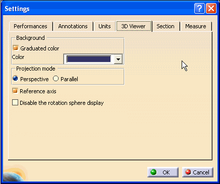
3D Viewer - You can change the background color and pattern of the viewer. The 3D model view display can be repositioned by projection, axis position, rotation, and animation speed.

Units - You can change the numeric display of measurements and calculations. Trailing zeros, exponential notation, and decimal location can be modified.

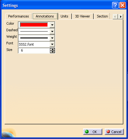
Annotations - The Annotations option affects the line characteristics in a model, including color, weight, and font.

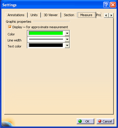
Measure - Measurement notations can be modified by changing line width and text color.

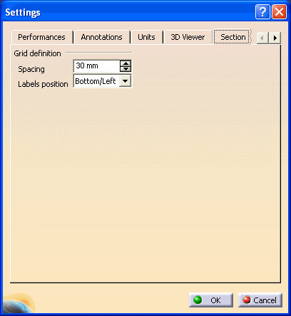
Section - The spacing between grid lines and adding grid labels can be changed with the Section option.

Product List -  - You can generate or modify a product list for the model.

Performances - You can change the system performance characteristics by modifying detail levels, pixel culling, surface lighting, and back face culling.

Note: The tabs in the Settings dialog box are added dynamically when the corresponding object is first added to your view.  Settings dialog box will show the last tab opened previously during the session.  Use left arrow, located next to tabs, to view all of the available options.  Tabs are shown in the alphabetical order.

How to Modify 3D Viewer Settings

You can modify the 3D viewer settings by following the steps below:

  1. In a 3D Viewer, click the Settings  button. The Settings dialog box appears.

  1. Click the 3D Viewer tab from the Settings dialog box.

  2. Modify the settings as described below.

Background color

Modify the Background color to the color of your choice.

Click the Color selection button and choose the desired standard color from the proposed list.

Graduated color

On - the background color will be graduated
Off - the background color will be solid

Projection mode 

perspective - view with perspective
parallel - view in parallel

Note: When you are working in either Walk or Fly mode, the projection mode is automatically set to Perspective and the Projection mode setting will be grayed.


Reference axis 

On - display reference axis
Off - do not display reference axis

Rotation sphere display 

On - display bounding sphere when rotating
Off - do not display bounding sphere when rotating

Note: The calculated animation time for a given product impacts the number of animation steps. The longer the calculated duration, the fewer steps. In the case where the animation would take too much time, there will be no viewpoint animation.


  1. To apply the modified settings and close the Settings dialog box, click the OK button at the bottom-right of the dialog box.

How to Modify Units Settings

You can modify the unit settings by following the steps below:


  1. Click the Units tab from the Settings dialog box.

  1. Modify the settings as described below.

Units

  1. In the Magnitude column, click the magnitude type to modify the unit of measure.

  2. At the lower-right of the Units area, click the units selection button and select a value from the proposed list.

Display trailing zeros

True - display trailing zeros of analyze results
False - do not display trailing zeros of analyze results 

Exponential notation for values greater than 10e+

Enter the power of 10 for large analyze results to be displayed in scientific notation, e.g. the default value 6 indicates that results will be displayed in scientific notation as of the value1,000,000 (10 raised to the 6th power).

Exponential notation for values lower than 10e-

Enter the power of 10 for small analyze results to be displayed in scientific notation, e.g. the default value 6 indicates that results will be displayed in scientific notation as of the value 0.000001 (10 raised to the -6th power).

Same display for read/write numbers and read only numbers 

On - display in similar manner (as defined for read/write numbers)
Off - display each in its own manner

Decimal places for read / write numbers

Enter the number of decimal places you wish to be displayed for numbers that appear in text-entry fields (numbers that you can write). 

Decimal places for read only numbers

Enter the number of decimal places you wish to be displayed for results (numbers that you can only read).

  1. To apply the modified settings and close the Settings dialog box, click the OK button at the bottom-right of the dialog box.

How to Modify Annotation Settings

You can modify annotation settings by following the steps below:

  1. Click the Annotations tab from the Settings dialog box.


  1. To modify the Color, Dashed, Weight or Font settings, click the appropriate selection button and choose the setting from each proposed list.

Note: Line thickness (weight) can only be modified for font type STROKE. For all other font types, modifying the line thickness will have no effect.


  1. To modify the annotation size, enter the desired value in the Size text-entry field or use the Increment/Decrement     buttons to obtain the desired value.

  2. To apply the modified settings and close the Settings dialog box, click the OK button at the bottom-right of the dialog box.

How to Modify Measure Settings

You can modify measure settings by following the steps below:

  1. Click the Measure tab from the Settings dialog box.

  2.  

  1. To modify the Color  (measure color), Line width or Text color settings, click the appropriate selection button and choose the desired setting from the proposed list.

  2. To see the "~" symbol to indicate approximate measures, select the Display ~ for approximate measurement checkbox.

  3. To apply the modified settings and close the Settings dialog box, click the OK button at the bottom-right of the dialog box.

How to Modify Section Settings

You can modify section settings by following the steps below:

When you load large models and are using the grid for visualization purposes, the interval between lines of the grid will be adjusted as necessary to fit the entire model in the viewing space. Therefore, the interval might not correspond to the interval specified in the Settings. (If you zoom in close enough that the specified interval can be used, the grid interval will automatically revert to the specified value.)

  1. Click the Section tab from the Settings dialog box.


  1. To modify the spacing value between grid lines, enter the desired value in the Spacing text-entry field or use the increment/decrement buttons to obtain the desired value.

  2. To modify the positioning of the grid labels, click the Labels position selection button and choose the desired setting from the proposed list.

  3. To apply the modified settings and close the Settings dialog box, click the OK button at the bottom-right of the dialog box.

How to Modify Product List Settings

You can modify product list settings by following the steps below:

  1. Click the Product List tab from the Settings dialog box.


  1. To work with a free-floating dialog box, click the Dialog Box option button, or, to work with a product list immersed in the Web Space, click the Immersive option button.

  2. For the Product List text to be self-determining, click the Text-dependent option button, or, in order to determine a fixed size for the Product List text, click the Fixed option button and enter a character size in the characters text-entry field.

  3. To apply the modified settings and close the Settings dialog box, click the OK button at the bottom-right of the dialog box.

How to Modify Performance Settings

System performance can be improved by modifying the performance settings and adjusting the display quality of the viewer. You can modify performance setting by following the steps below:

  1. Click the Settings button. The Performance Settings page will be the first settings page displayed.


  1. The Level of Detail option provides the ability to vary the viewer display performances of a model.

  • Static provides the option of adjusting the amount of detail in a model. Move the slider to increase the value and reduce the level of detail. Values range from 0 (fully-detailed view) to 40 (minimal detailed view).

  • While Moving provides the option of moving larger parts more quickly. Move the slider to increase the speed of moving a part. If the mouse is released after moving the part, the normal level of detail will be redisplayed. Values range from 0 (normal part speed) to 40 (maximum speed).

Upon releasing the mouse in both instances the model will reappear.

Note: In both cases, the higher the value, the lower the level of detail. Normally, the Static will have a lower value and the While Moving will have a higher value, providing increased display performance of the viewer.

When using the Level of Detail  (LOD) option, ensure that the CGR files contain LOD information. This is done during the CGR creation.

When working with a model that has several colors applied (for example: a different color for each surface) using a static or dynamic level of detail, only one color will be displayed for performance reasons. The dominant color used in the model will be the color used in the display.


  1. The Pixel Culling option performs similarly to Level of Detail, however it defines the size in pixels of objects to be hidden or displayed, and affects the display performances of a model in the viewer.

  • Static provides the option of adjusting the pixel quantities to be displayed in the viewer. The smaller the value the more details with smaller pixel quantities appear. The larger the value and only the features with the larger pixel quantities will appear. A larger value will display only the details of the model with that minimal pixel size and the view will be generated faster. Values range from 0 (fully-detailed view) to 40 (minimal detailed view).

Note:  Selection points may not be visible when the Pixel Culling - Static  is set to the maximum value.


  • While Moving provides the option of moving larger parts more quickly. Move the slider to increase the speed of moving a part. If the mouse is released after moving the part, the Static size will reappear. Values range from 0 (normal part speed) to 40 (maximum speed).

  1. The Enable two side lighting for faces and surfaces only option that helps you to visualize the two sides (i.e. front side and back side) of a face or surface by lighting them.

  2. The Enable back face culling option provides different selection options for surfaces to be displayed.

  • For stand-alone  faces provides a view of only the front face of the surface without displaying the back sides of faces or surfaces. This option also helps clarify the model displaying the faces and surfaces used to define the model.

  • For faces belonging to solids provides the option of displaying the faces and surfaces used to define the model. If this option is selected, back sides of faces or surfaces belonging to solids are not displayed.

Note: Some of the performance settings (Pixel Culling and Level Of Detail) will enhance performances. Whereas, Back Face Culling will have an impact on the performances mainly because the faces that were not previously drawn (because they were not visible) will be systematically rendered. This decrease in the performance is totally dependent upon the model size.