 |
This task shows you how to generate the base curves of the plies
contours by slicing the solid.
The height of each ply is computed from the
solid and the thickness law information.You can generate several
Slicing Curves Group features in a CATPart, e.g. to support
collaborative design:
several designers would slice portions of the solid
and then reconciliate the curves through the merge contour tools.
Slicing Curves Group features have their own update
mechanism that lets you track and decide which changes of their inputs
need to be applied downstream. |
 |
-
Click Slicing Group
 .
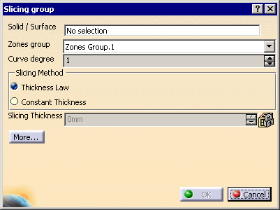
The Solid slicing dialog box is displayed. .
The Solid slicing dialog box is displayed.

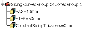
A node Slicing Curves Group of Zones Group.1 is created in the
specification tree.

|
It contains two parameters,
SAG and STEP:
|
-
Select the solid you want to slice.
-
Select the
zones group corresponding to the solid: the
thickness of the solid must correspond to the thickness laws of the
zones.
-
Select a
Slicing Method:
- Thickness Law
(recommended).
To use this method, the zones in the zones group selected must
comply with the staggering rule.
This method support multi-material zones scenarii. Material and
direction information will be applied to the plies.
- Constant Thickness.
To be used if the zones do not comply with the staggering rule.
The contours of the plies will be generated using this constant
thickness.
Note that the plies will be generated with no material and
no direction information.
Only the generated contours will be
applied to the plies.
If you select this method, key in the
Slicing Thickness.
|
-
Select a
Curve degree: the contours are
computed from the discretized view of the upper surface of the solid and
smoothed using this curve degree.
-
If necessary, click More... and select or
clear the Reduce micro edges check box:

- By default, this check box is not selected. The slicing is
done patch by patch (by patch, we mean the patches supporting the
surface).
- If you select this check box, the underlying patches are
grouped by tangency continuity. This is useful with a surface with
many underlying patches as it reduces the number of edges on the
contour and removes micro-edges.
When working with very taut parts, be careful not to select this
check box if you have set the Curve degree to 1: the result would be
too simplified, the curves would no longer follow the design. |
-
Click OK.
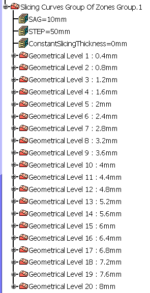
The curves are created under the node Slicing Curves Group of Zones Group.1.
They are grouped by Geometrical Level, each one corresponding to an
"altitude" of the contours.
Hide/Show is available on each Geometrical Level node.

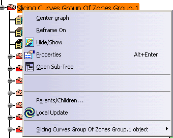
A contextual menu is available to delete a Slicing group:

|