in a separate .CATPart document, keeping the link to the engineering .CATPart.
![]()
Open the ManufacturingData1.CATPart document.
- When the manufacturing preparation part is generated/synchronized, identification information is added to the engineering part. This information is absolutely necessary to allow the composites entities to be recognized (and therefore not recreated) during future synchronizations. Therefore, it is mandatory to save the engineering part if the long warning message appears.
- To avoid the long warning message, launch the c:prepare for
synchronization command from power input. This concerns
- the engineering designer before generating the manufacturing preparation part,
- or the manufacturing designer before the synchronizing the manufacturing part.
-
Click the Creates manufacturing Document icon
 .
.
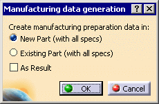
The Manufacturing data generation dialog box is displayed.

-
Choose whether you want to create the manufacturing data in a new or an existing part.
-
New part (with all specifications):
a new .CATPart document opens and manufacturing data are created in this part. -
Existing part (with all specifications):
this option is useful if you want to generate the manufacturing preparation data in a precise CATPart.
The File Selection dialog box is displayed.
Select a CATPart document. Click Open.
Manufacturing data is created within this part.
-
New part (with all specifications):
-
Click OK.
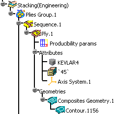
The engineering part contains: - preliminary design data (zones, transition zones, ITPs),
- the engineering definition of the plies in the stacking
(Composites Geometry, Contour).

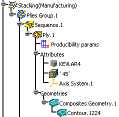
The manufacturing part contains:
- the manufacturing definition of the plies in the stacking
(Composites Geometry, Contour).

- core samples and numerical analysis will not be generated in the manufacturing preparation data.
- only a simple copy (with no link) of the producibility parameters will be generated.
The Skin Swapping and Material Excess icons are available in the Manufacturing Toolbar.
![]()