 |
This task shows you how to create iso-thickness areas. |
 |
Open the
GridSolidGA01.CATPart
document. |
 |
-
Insert a Geometrical Set in the specification
tree, name it IsoThicknessPoints and make it the In Work
Object.
-
Click Create iso-thickness areas
 . .
The
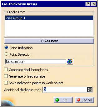
Iso-thickness Areas dialog box is displayed:
The
Plies Groups found in the model are displayed in the dialog box.
If necessary, select the one from which you want to create the iso-thickness
areas.
-
Click 3D Assistant.
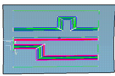
The model is updated and a first group of iso-thickness areas is
computed and displayed in the 3D Viewer:
-
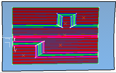
For each identified iso-thickness area, pick a point
(core sample) as shown below:
You can either:
- select Point Indication and pick the reference
surface where you want to create the core sample point (the point
does not exist yet),
- or select Point Selection and pick existing points.
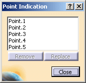
- Multi-selection is available through
 and the dialog box below:
- A contextual menu is available:
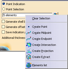
- As soon as you have picked a point on one of the iso-thickness
areas proposed in the step above, this area turns red to prevent
another pick on the same area.
|
-
Select the Generate shell boundaries check
box to create the boundaries of the iso-thickness areas.
-
Select the Save indication points in work object
to create the points in the current In Work Object (see step 1). You can thus
reselect all those points in one-shot if iso-thickness areas need to
be recreated.
-
Click OK. If necessary, select the kind of synchronization in the
message that is displayed. The iso-thickness areas are created:
|
In each iso-thickness area node, you will find:
- the thickness of the area,
- the boundaries of the area,
- the Additional thickness ratio. By default, it is
set to 0. It can be modified at the creation of the iso-thickness
areas, or later.
The core sample points are either stored under the iso-thickness
area node if Save indication points in work object
was not selected:
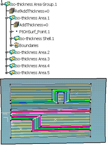
or under a single In Work Object if Save indication points in work object
was selected:
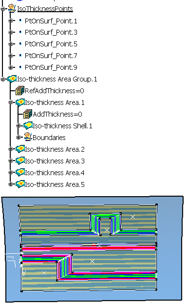
|
|
 |
The contour of the iso-thickness area is relimited by:
- the bottom of the ramp (i.e. last ply+1 on ramp support) if the
plies are created with the grid approach (i.e. if they are based on ramp
support). In that case, the iso-thickness area turns yellow. If the iso-thickness
area cannot be relimited by the bottom of the ramp, it turns pink.
- the last ply contour if plies are not created with the grid
approach, or if plies have been modified with non-grid approach tools
(e.g. limit contour).
- iso-thickness areas that are only relimited by the last ply contour
will have a different color so that you can identify them and rework
them.
- a warning will be issued if an iso-thickness area needs to be
reworked.
- you can modify the shape of an iso-thickness area before creating
the solid.
- when the core sample point of an iso-thickness area may have become
invalid, a mask at the iso-thickness area node indicates that the
feature needs to be updated:
- double-click the feature to edit it,
- check the location of the core sample point,
- click OK to run the computation and update the feature.
- if you modify an iso-thickness area, and add or modify core sample
points, iso-thickness areas that have not been impacted do not need to
be recomputed.
Selecting Imposed thickness points is optional. Selecting
some allows you to manage ramps that do not follow a linear law (e.g.
because a manual ply has been added), or ramps at the edge of the part. |
|
 |