 |
This task shows you how to:
|
 |
- For a problem-free generation of plies, we recommend that:
- the cells are defined by a closed contour made of at least 2
reference elements,
- the cells should not use more than two nodes per reference
elements (e.g. L-shape cells are OK, U-shape cells are not).
- The definition of the limitation side of limit contours is taken
into account.
- If you generate a second plies group from a virtual stacking that
already contains a plies group, only the plies group created first will
be synchronized with the virtual stacking (the second one will not be
synchronized).
|
 |
You must have created a virtual stacking. Open the
RampSupportGA.CATPart
document. |
|
|
-
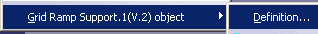
Right-click a ramp support in the specification tree and
select Definition in the contextual menu:
or double-click a Grid Ramp Support node,
or pick Grid Ramp Support definition
 and select the ramp support to edit.
The Grid Ramp Support Definition dialog box is displayed:

-
Select the Structural element on which the ramp support
will be computed.
-
Decide on which side the ramp will be (Side + or Side -)
-
If required, define a
Ramp Support Fallback Strategy.
Create Ramp Support Curves Automatically
-
Make sure Automatic ramp curves creation
is selected. -
By default, the Clearance and slope identical to
structural element check box is selected, meaning all the ramp
supports will be created with the same clearance and slope as those of
the structural element. Modifying the structural element will thus
update the ramp supports. -
Clear this check box if you want to modify the clearance
type and its value, as well as the slop value:
- Define the type of ramp support:
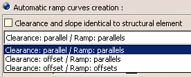
-
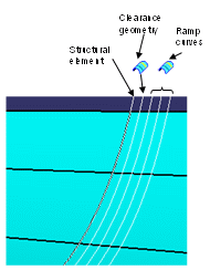
clearance: parallel / ramp: parallels
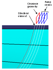
- clearance: offset / ramp: parallels

- clearance: offset / ramp: offsets
-
Define the first curve, either by a distance from the
clearance area or by a point (for 45 degrees cut).
-
Define the Slope value:

|
-
Define the number of curves (Curves count).
-
Define the geometry creation options:
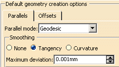
-
Click OK to validate and exit the dialog box.
Create Customized Ramp Support Curves
-
Select Custom curves creation.
Another Grid Ramp Support Definition dialog box is displayed:
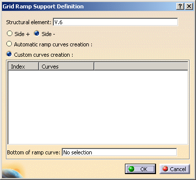
-
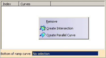
Select existing curves or use the contextual menu to
create some:
-
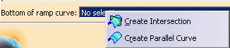
Select a bottom ramp curve or use the contextual menu to
create one:
-
Click OK to validate and exit the dialog box.
|
|
 |