Case with one part:
- When a part with linked 3D Annotation is hidden, the annotation is also hidden.
- When the part is shown, the linked 3D Annotation is also shown.
Case with several parts:
- If one of the parts is hidden, the line joining the part and the 3D Annotation will also be hidden.
- If all the parts linked to the annotation are hidden, the 3D Annotation is also hidden.
- As soon as one of the linked parts is shown, the 3D Annotation is also shown.
-
Select Insert > 3D Annotation from the menu bar or, in the DMU Review Creation toolbar, click the 3D Annotation icon
 .
.
-
Click an object at the point you want to place the text. (Note: You can select the object first. )
The Annotation Text dialog box and the Text Properties toolbar appear.

Inserting symbols (Windows only)
You can insert symbols in annotated views.
- Choose the SymbC font. The symbol at the right of the Text Properties toolbar will now be selectable.
- Click the arrow in Insert Symbol icon to select a symbol from those proposed:

|
|
Using symbols forces the font to change to SymbC and can create problems if text will be associated to the added symbol; the only font that can be used with symbol is SymbC. |
-
Enter the desired text in the 3D Text field.
Note: you can now change the font size and type if desired using the Text Properties toolbar.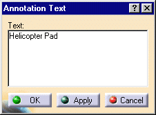

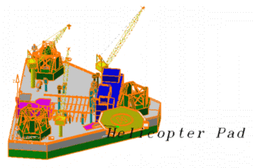
-
Use the green manipulator to position your 3D text.
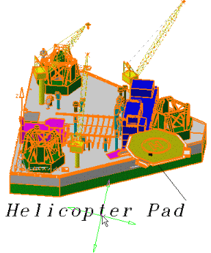
-
Click OK when satisfied.
The text is added at the desired position. Annotations are attached to the point selected. You can move your document: annotations remain attached to the point at which you place them.For more detailed information about moving annotations, please refer to Managing 3D annotations.

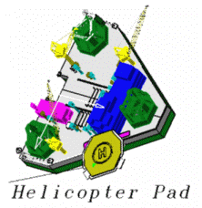
Note: Text annotations are identified in the specification tree.

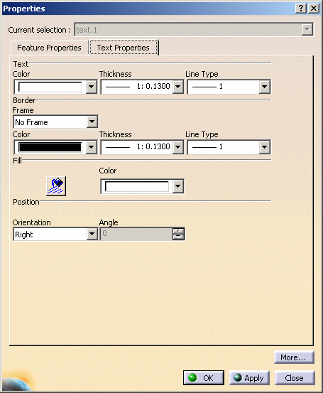
A text's drawing properties include its color. You can change the color of text that you've already added. You can add a frame, define properties for this frame ( line type and thickness), fill it with the desired color and even change the orientation of the 3D text.
-
Right-click a text you've already added and select Properties from the contextual menu, or click the text and select Edit > Properties from the menu bar.
The Properties dialog box appears. Note: Dynamic highlighting as you move your cursor over objects helps you to locate them. -
Click the Text Properties tab.
-
Make desired changes (e.g. add a Frame).
-
Click OK when done.

- If the background color is modified, the white color for annotations will not be automatically modified to accommodate the modified background. You must modify the annotation color manually.
- Line thickness can only be modified for font type STROKE. For all other font types, modifying the line thickness will have no effect.
- To modify text, double-click it.
To delete annotation text, right-click the object and then select Delete from the contextual menu. - Size of 2D annotation text and 3D annotation text can be different for same font size.
![]()