An aligned section view / cut is a view created from a cutting profile defined from non-parallel planes. In order to include in a section certain angled elements, the cutting plane may be bent so as to pass through those features. The plane and feature are then imagined to be revolved into the original plane.
-
In the Drawing window, click Aligned Section Cut
") in the Views toolbar (Sections sub-toolbar).
in the Views toolbar (Sections sub-toolbar). If desired, you can also click Aligned Section View
") .
.
Define a profile, by creating one or several lines by creating a point first and then further creating the complete profile. -
Create the first point of the profile. The Tools Palette is displayed with constraint options (Parallel, Perpendicular and Angle). By default, the active constraint is the Parallel. You can choose any one constraint.
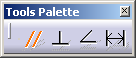
- Parallel: The profile segment is created parallel to the selected reference element and passing through the first point.
- Perpendicular: The profile is created perpendicular to the selected reference element and passing through the first point.
- Angle: If the angular
constraint is selected the angle definition box pops up
allowing you to enter the desired angle.
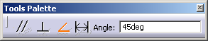
By default, the angle is set to 45 degrees for the first angular constraint, and then it keeps the previous value entered for any further angular constraints. The angle defines the direction counter clockwise for the current profile segment relatively to the selected line.
-
-
Choose the constraint. You have to select a valid element to set the direction of the profile which can be:
-
a generated line, in this case the constraint is associative to the 3D geometry
-
one of the coordinates axis of the sheet (no associativity)
-
a interactive 2D line (no associativity).

Selecting a constraint keeps the Tools Palette hidden, as long as the second point of the current line is not created.
-
-
Tools Palette becomes active again to allow you to select another constraint for the next line.
-
-
-
-
-
-
If you are not satisfied with the created profile, you can at any time, use Undo
 or Redo
 ") .
Note that
SmartPick assists you when creating the profile.
.
Note that
SmartPick assists you when creating the profile. - Once the profile is created, the constraints associated can be deleted in edit mode but cannot be modified nor recreated unless you recreate the whole profile.
- If the 3D geometry to which the profile is associative is deleted, then the profile is still available, but is not associative and the constraints are shown in edit mode.
- You can select a cylindrical surface, which is projected as a 2D edge as the reference element for applying a section constraint. In this case, the constraint is always applied to the axis of the selected cylindrical surface.
The section plane also appears on the 3D part and moves dynamically on the part.
-
-
Double-click to end the cutting profile creation.
Positioning the section view amounts to defining the section cut direction. The cutting profile is hole associative. -
Click in the drawing to generate the view.

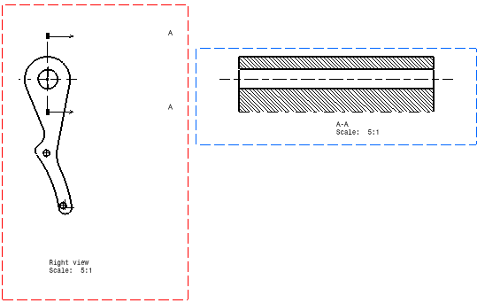
About Aligned Section View / Cut
Contrary to other view types, in an aligned section view/cut, the 2D geometry seen in the view is not based on a single 3D plane, but on numerous 3D planes. However, as all generative views, the aligned section view represents only one projection plane. Then it selects only one of the 3D planes (the one corresponding to the first segment of its profile). As a consequence, some results can be different from the user's expectations:
-
Symbolic representation of threads can be malformed,
-
When creating an auxiliary, section, breakout or box clipping view from the aligned section view/cut, the result might not be the one expected by the user.
In these particular cases, a view of each part would give expected
results.
Aligned section views through circular and cylindrical elements
- a generated circular item or a center line
- a generated item corresponding to a revolution surface or an axis line.
-
In the Drawing window, click Aligned Section Cut
in the Views toolbar (Sections sub-toolbar).
If desired, you can also click Aligned Section View
. -
Select first the circle representing the hole (or a center line), to define a profile going through the hole.
The first extremity of the segment is positioned automatically outside the geometry.
Double-click to end the profile.
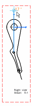
In this case, you can see that the top position has been fixed.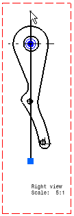
-
Drag the blue manipulator to define the cutting length.
In this case, the second extremity is placed inside the geometry.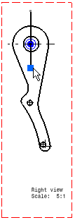
Double click to end the profile.
-
Click in the drawing to position the view.
About Patterns
The patterns, which are used to represent the section, are defined in the standards. For more information, refer to Pattern Definition in the Interactive Drafting User's Guide.
You may modify the pattern (hatching, dotting, coloring or motif) by right-clicking the pattern and selecting Properties from the contextual menu. This will display the Properties dialog box in which you may either select a new pattern or modify some graphical attributes of the existing pattern. For more information, refer to Modifying a Pattern.
About the Cut in section views capability
In an assembly, you can define that given parts will or will not be sectioned when generated into section views. (This capability is not available for section cuts.)
In the Assembly Design workbench, select one part, then the Edit > Properties command from the menu bar from and either activate or de-activate the Cut in section views option. You can also do this when overloading element properties in a view generated from a CATProduct.
If you choose to not cut elements in section views (i.e. if you uncheck the Cut in section views option), note that if the cutting profile intersects an uncut part, then this part will not be cut and will be entirely projected.
About section views or section cuts generated using the Approximate generation mode
You can now generate section views or section cuts using the Approximate generation mode. For more information on the approximate generation mode, refer to Customizing Settings: View.
|
|
There is no associativity or detection on generated geometry in case of CGR/Approximate/Raster views. For these views, there will only be detection on interactive geometry and axis. |
When generating section views or section cuts using the Approximate generation mode, or when switching a section view/cut from exact mode to approximate mode (i.e. via Edit > Properties), be aware of the following information:
Patterns
In the case of parts, which use a material to which a specific pattern is associated, section views/cuts in Approximate mode do not inherit the material properties from the 3D, and therefore do not use the pattern associated to this material.
Pattern properties are not persistent: for instance after switching an exact view to the approximate mode, and vice versa, the pattern may change.
The Cut in section views capability
If you choose to not cut elements in section views (i.e. if you uncheck the Cut in section views option), note that this capability does not work for section views generated using the Approximate generation mode: selected elements will be cut. Likewise, if you switch an exact view to the approximate mode, the elements for which you unselected the Cut in section views option will be cut in the view.
![]()