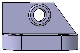
Open the Pinmounting_constraints.CATDrawing and load the linked CATPart document using Edit > Links.
Select the Display constraints check box from Tools> Options>
Mechanical Design> Drafting> Geometry tab, Constraints Display
area.
Constraints between the 2D geometry and generated elements have been
created in the CATDrawing.
-
Modify the generative geometry by modifying the CATPart as shown:

-
Click Update
 in the Update toolbar.
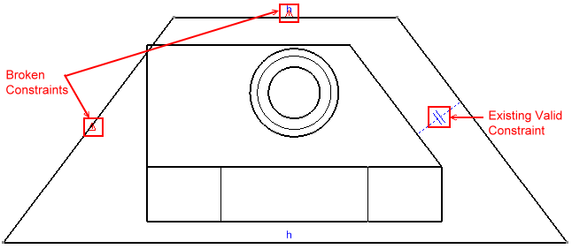
You can see that the broken constraints are represented by a red warning symbol and other valid constraints are also seen.

More About Broken Constraints
- The following six types of broken constraints are represented: parallelism, perpendicular, coincidence, concentric, tangency and symmetry.
- Broken constraints are represented by
a red warning symbol
 .
. - The broken constraint symbol is located in the middle of the curvilinear parameter of the geometry.
- To find out the original type of the constraint, move the mouse over the broken constraint symbol and the current pathname of this object is seen in the status bar.
- In case a use-edge is deleted the constraint created with it is also broken.
- When the geometry and its broken constraint are included in the selected trap for copy, constraint is kept and is pasted too. If the entire geometry is not copied and pasted, the constraints are not copied.
- You can delete a broken constraint; select it and use the Delete contextual menu or press the Delete key.
- If the geometry is deleted, the associated constraint is also deleted.
- The color of broken constraint is same as inconsistent elements as in Tools > Options > Mechanical Design > Drafting > Geometry tab, Colors area, Visualization of diagnostic.
- The size of broken constraints is same as normal constraints (2mm by default) in Tools > Options > Mechanical Design > Drafting > Geometry tab, Constraints Display area, Reference size.
![]()