![]() |
In this task you will learn how to create a line. | |
![]() |
You will need to display the Horizontal (H) and Vertical (V) fields in the Tools palette, as they are displayed optionally. To do this, go to Tools > Options > Mechanical Design > Drafting > Geometry tab and select the Show H and V fields in the Tools Palette option. | |
![]() |
1. Click the Line icon
![]() |
![]() |
The Tools palette appears, displaying the Start Point value fields: | ||
![]() |
||
2. Enter the line start
point coordinates. For example, H: 1.625in and V: 0in. 3. Press Enter. 4. Enter the end point
coordinates in the Tools Palette.
For example, H: 2.362in
and
V: 0in. |
||
In this particular case, smartpicking is
used for creating the line. The constraints in smartpicking are defined such that we can create a line parallel to one of the rectangle lines. In this case of smartpicking the parallelism symbol ![]()
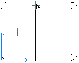
|
![]() |
|
|