The portion of mesh locally modified will pass through one or several points or a curve.
-
Click Mesh Morphing
 .
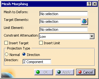
The Mesh Morphing dialog box is displayed:
-
Select Tessellation.1 as the Mesh to Deform.
You can select only one single mesh. -
Select 3D Curve.1 as the Target Element.
The Target Element can be one or several points, or one curve, or a cloud of points through which the output mesh will pass.
If you select a cloud of points as the Target Element, be careful that the cloud contains a moderate number of points.
-
Optional: Select Curve.1 as the Limit Element. See About Limit Element for more information.
-
Select a type of Constraint Attenuation from the drop-down list:

Constraint Attenuation lets you control the shape of the mesh morphing. The higher the Constraint Attenuation, the smaller the mesh deformation, i.e. select a Low Constraint Attenuation for a greater mesh deformation, and a Very Strong Constraint Attenuation for a smaller mesh deformation.- Low:

- Very Strong:

- Low:
-
-
-
Select the Projection Type:

By default, it is set to Direction, and Z Component.
A contextual menu is available:

-
Click Apply:
- The Target Element (one or several points or a curve) is projected into the Mesh to Deform according to the specified direction. This projection acts as a handle.
- Then the mesh is deformed within the Limit Element as if you were dragging that handle to the Target Element.
- Tangent continuity is ensured between the deformed mesh and the non-deformed mesh which lies outside the Limit Element.
-
Click OK to validate and exit the dialog box.
About Limit Element
When selected, the Limit Element defines an area inside which the vertices of the mesh can be moved while those outside the area remain untouched.
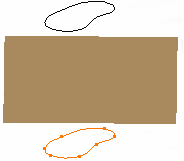
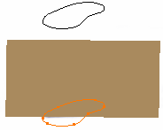
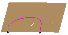
When selected, the Limit Element or its projection on the mesh according to Projection Type must lie completely on the mesh.E.g., the two cases illustrated below are not allowed:
If you do not select a Limit Element:
- The boundary of the Mesh to Deform acts as the Limit Element.
- If the Mesh to Deform has several boundaries, the longest boundary is used as the Limit Element.
- If the Mesh to Deform does not have any boundary (closed volume mesh), an error message is displayed and you are requested to select a Limit Element.
If the Limit Element does not lie on the Mesh to Deform, it is projected on the Mesh to Deform according to the Projection Type.
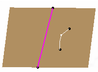
The Limit Element is not necessarily closed. An open
Limit Element (pink curves in the following figures) which cuts the
mesh into two areas is allowed. But the target element (white curve and
points), once projected, must lie entirely inside one area.
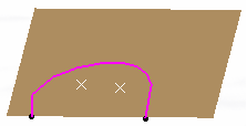
The following cases are not allowed::
- the Target Element does not lie within one area.

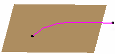
- the Limit Element does not define areas:
- the Limit Element lies on several zones:
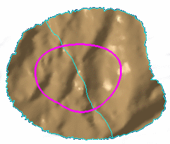
This can be solved using the Mesh Cleaner in Digitized Shape Editor.
![]()