Copying/Pasting Elements

This task shows how sketched elements behave when you copy and paste them. More specifically, you will learn about:

For general information on copy/paste, see the Infrastructure User's Guide.

Copying/Pasting Elements with H and V Constraints on Their Absolute Axis

This task shows you how to copy/paste elements along with the horizontal and vertical constraints on their absolute axis.

Open the Copy_paste_H_and_V.CATPart document.
  1. To duplicate the rectangle and its H and V directions: multi-select the rectangle and its origin, and copy the selected elements.
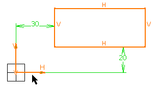
 

OR

  1. To duplicate the rectangle, its H and V directions, and the distance constraints which exist between the rectangle and its origin: multi-select the rectangle and the distance constraints (do not select the origin), and copy the selected elements.
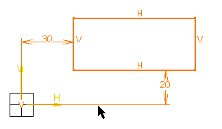
 

In other words, if you want to copy an element along with its H and V direction while keeping the constraints which exist between the copied element and its origin, you do not need to, and you should not, select the origin. Selecting the constraints is enough. If you select the origin, the constraints will not be kept.

  1. Paste these elements.
    The elements are pasted over the elements you copied. You can move the pasted elements (if you want to view them, for example).

Copying/Pasting Projected or Intersected Elements

This task shows how sketched elements that were created via projection or intersection behave when copying/pasting them.

  1. Copy the projected or the intersected element, using the method described above.

  1. Paste this element.
    External references are deleted:

  • Constraints on external geometry are deleted.

  • Projections/Intersections are deactivated when they have external references.

  • You cannot project or intersect the pasted element.

  • The pasted element is not associative.


Copying Sketches

This task shows how pasted sketches behave.

  1. Create a sketch then enter Part Design workbench.
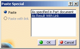
  1. Copy and paste the sketch using the Paste Special contextual command and the As Result with Link option.


The sketch is pasted. You can observe a blue symbol added to the image of the sketch in the specification tree, meaning that associativity is maintained between the reference geometry and the copy.
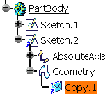
 
  1. Use this copied sketch to create a pad.

  1. Just edit the reference sketch the way you want: for example, change the shape. The pad reflects the change.

In the specification tree, sketches copied and pasted in documents different from the documents in which they were created are identified by a green point in target documents:

The green point is turned into a red cross when the copied sketch needs synchronizing with its reference:


Explode

The Explode capability allows you to edit and modify a sketch obtained by Copy>Paste>As Result With Link. Exploding the sketch converts every wireframe geometry associated to the datum feature into a standard 2D geometry feature and the copy feature is then removed from the specification tree. Consequently, there is no more associativity between the exploded sketch and its reference sketch.

Exploding Sketches

To explode a sketch, right-click it from the specification tree and select Sketch.XXX object > Explode...

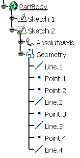
The specification tree is as shown after the explode operation:

When done:

  • The sketch is not-up-to-date.
  • The order and the number of geometrical elements appearing in the specification tree after an explode operation may differ from what can be seen in the reference sketch.
  • Exploded sketches used by Part Design or Generative Shape Design features appear in Update Error dialog boxes. You need to reroute them one by one.

More about Exploding Sketches

A sketch obtained by Copy>Paste>As Result With Link is a copy of its reference sketch. By default, the system keeps associativity between the resulting sketch and the original geometry as well as between resulting sketch position and the position of the sketch reference.

To manage this associativity, such sketches contain datum features which are the real features keeping associative links between the copies and reference sketches. 3D geometrical results associated to reference sketch features are duplicated and associated to these datum features.
Thus associativity:
With the original geometry is controlled by these datum features managing associative copies of the 3D geometrical
results associated to reference sketches. Consequently they cannot take into account the following data that is included in reference sketches:

  • Construction or axis line geometrical elements.
  • Geometrical elements on which output or output profile features exist.
  • Constraints and dimensions.

Associativity with the original geometry is always kept till it is not removed using Isolate. By the way, geometrical results can be different from reference sketches until datum features are not synchronized with reference sketches.

With the original sketch position is managed by the sketch absolute axis feature definition. By default it is defined as associative in position with its datum feature, thus with its reference sketch feature position. But you can break this associativity if needed by defining your own sketch position. Since V5R19, thanks to the Sketch As Result With Link positioning capability, associativity with original position is explicitly identified via Positioned as reference support definition mode or can be retrieved afterwards using this new definition mode.