![]()
This task shows you how to extract geometrical or electrical bundles with all the devices that are associated to them, such as their connectors, back shells, shells, contacts and supports from a 3D model.
![]()
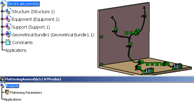
Open the
ElectricalAssembly.CATProduct document.
Keep open the Flattening Assembly document you have created in the
previous task.
If you have forgotten to open a second document, a warning message will be displayed.
![]()
-
Select Windows > Tile Horizontally to get a better viewing of the process.

-
- There are three types of extraction modes:
- New From
- Synchronize (with mechanical constraints)
- Synchronize (without mechanical constraints).
For more information see Electrical Harness Flattening.
-
It enables you to extract the information contained in the geometrical or the electrical bundles from your first document.
-
When duplicating an electrical bundle, all the links with the geometrical bundles associated to it are maintained.
- There are three types of extraction modes:
-
Select an electrical or geometrical bundle in the geometry area or in the specification tree.

-
Selecting the Electrical connection check box in Tools > Options > Equipment & Systems > Electrical Harness Flattening > General tab allows the system to automatically check the electrical connections. For more information refer to Electrical Harness Flattening.
-
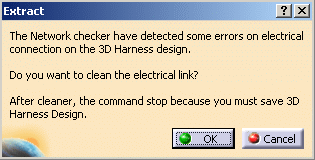
By default, the system checks for electrical connections. If errors are detected in the 3D harness, a dialog box is displayed informing that errors are found, and need to be corrected:

-
If you click OK, the errors are corrected.
-
If you click Cancel, the extraction process stops and no further action is taken.
-
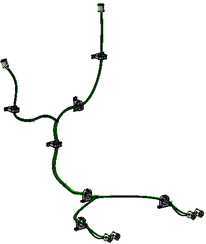
The result looks like this.

-
-
Save your data.
- While using the Extract command on documents
created in V5R11, an error message may appear saying: An error has occurred
during the data duplication.
You can try to use the CATDUA utility to clean the data and recover the correct geometry.
Refer to Using the Data Upward Assistant. - Make sure that only one document corresponding to 3D Install Harness assembly (products and parts) is opened in the editor at the time of performing the extract. Else, there will be some errors during the extract process which may lead to corrupt data. However, if the user happens to commit this mistake, i.e. open 2 windows in 3D design data, an error message appears saying: An error has occurred during the data duplication. However, please note that this error box can come for other reasons also.
Extracting 3D Data using the Synchronize Algorithm
To use the Synchronize algorithm in order to ensure better PLM integration and obtain a HTML report on the Extract process, select the Synchronize option (Tools > Options > Equipment & Systems > Electrical Harness Discipline > Electrical Harness Flattening > General).