The Browse window is integrated to the Light Protective Covering command through the Light Protective Covering dialog box. It lets you select catalogs stored in database when working in ENOVIA context.
![]()
Open any document containing at least a geometrical bundle.
-
In the Electrical Harness Installation workbench, click Light Protective Covering
 in the Internal Protection toolbar.
For information on Tape Parameters, see About
Protective Coverings.
in the Internal Protection toolbar.
For information on Tape Parameters, see About
Protective Coverings.The Light Protective Covering dialog box appears:

-
Select the catalog then the Protective covering you want to instantiate.

You can instantiate protective coverings created using both the Define Protection Product and the Define Protection Part commands in the Electrical Library workbenches. However, if you use Define Protection Part, the customization of the reference part is not kept when instantiated. -
To do so:
- Click
 ,
and navigate to the catalog, for example:
.../online/cfysm_C2/samples/ElectricalSession/catalog. - Double-click the protective covering.
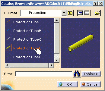
The catalog browser closes and the selected protective covering displays in the upper right corner of the primary window. 
If the Enable Sourcing access option is selected in the Tools > Options > Equipment & Systems > Electrical Harness Discipline > Electrical Assembly Design > General tab, the Collaborative Enterprise Sourcing (CES) environment is enabled, and the Sourcing Search dialog box is displayed instead of the Catalog Browser dialog box.


For a given part number defined in iXFElec file, there must be one and only one part found after the query on Internal Item Number criteria, else there would be an ambiguity.
- Click
-
An alternative is to use the Catalog Browser
 from the toolbar, select the protective covering then drag and drop
it onto the bundle segment:
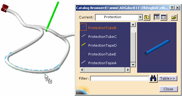

Supports can be added to bundle segments covered with a protective covering. If the support is adaptative, its parameters will be linked to the protective covering outer diameter.
-
-
In the specification tree, select one or more bundle segments to be covered with the protective covering.

- In case of multi-selection, the bundle segments must belong to the
same branch.
You can select normal bundle segments, as long as they are contiguous. - Light Protective Covering is a feature of a multi-branchable document, and it covers bundle segments in one branch only.
The Protective Covering Information is updated in the dialog box, and the protective covering start and end points are displayed in the geometry.
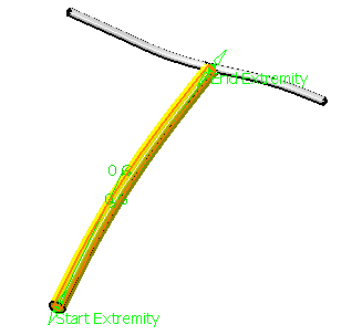
- In case of multi-selection, the bundle segments must belong to the
same branch.
-
Drag the Start Extremity or End Extremity label to modify the location of the internal protection.
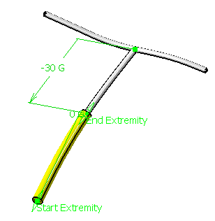
- The End Extremity here is modified.
- The protective covering turns to red informing you that it needs to be updated.
- The protection extremity is editable all along the branch.
- You can also double-click any one extremity to re-limit the protective covering.
- The Define Extremity dialog box appears:
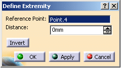
It lets you define the new position for the extremity from the reference point.
- Enter 30 mm in the Distance field.
- Click Invert to invert the position of the protection extremity to the other side of the reference point while maintaining the same distance from the reference point.
-
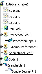
The light protective covering is added as a separate feature to the specification tree under the multi-branchable feature:
-
Light Protective Coverings integrate the collapsed geometry behavior (as applicable for external protections).
-
When you instantiate a customized internal protection (consisting of user defined parameters, relations, or rules), these parameters, relations or rules are added to the specification tree (under internal protection node). A view of the specification tree shows these parameters and relations added under the Product1.1 node:

-
Regarding Formula Creation using Attributes of Protection (External v/s Light Protection)
-
External protection instance is a part with electrical behavior whereas light protection is an electrical Feature.
-
Name of attributes realizing the same property across External and Internal Protection instances will be displayed differently in Formula Editor.
-
Following table provides mapping between analogous attributes of external and light protection instances, as visible in formula editor.
External protection instance attribute
Corresponding light protection instance attribute
Elec_External_Reference
External Reference
Elec_Length
Length
Elec_Line_Type
Line type
Elec_Line_Weight
Mass
Elec_Ref_PartNumber
Reference Part Number
Elec_Sub_Type
SubType
Elec_Bend_Radius
Bend Radius
Elec_Thickness
Thickness
Elec_Bend_Radius_Delta
Bend radius delta
Elec_Covering_Length
Overlapping length
Elec_Inner_Diameter
Inner diameter
Elec_Number_Layer
Number layer
Elec_Tape_Thickness
Tape thickness
Elec_Tape_Width
Tape width
Attributes common to Tape and corrugated protections
Attributes specific to corrugated tube protections
Attributes specific to Tape protections
-
