This task shows how to create a virtual rigid bolt tightening connection property between two parts.
-
Only available with the Generative Assembly Structural Analysis (GAS) product.
-
To have precisions and to know restrictions, refer to About Connection Properties.
Virtual Rigid Bolt Tightening Connections are used to specify the boundary interaction between bodies in an assembled system. Once the geometric assembly positioning constraints are defined at the Product level, the user can specify the physical nature of the constraints. When creating this connection, both the coincidence constraints and the Analysis Connections workbench constraints can be selected.

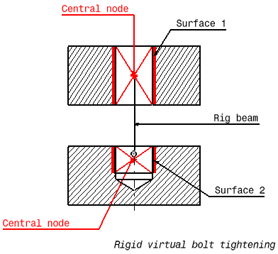
Surface 1 and surface 2 are supports for the assembly constraints of coincidence type.
A Virtual Rigid Bolt Tightening Connection is a connection that takes into account pre-tension in a bolt-tightened assembly in which the bolt is not included. The computation is carried out according to the two-step traditional approach. In the first step of the computation, the model is submitted to tension forces relative to bolt tightening by applying opposite forces on the first surface (S1) and the second surface (S2) of the assembly constraint, respectively. Then, in the second step, the relative displacement of these two surfaces (obtained in the first step) is imposed while the model is submitted to user loads. During these two steps, the rotations of both surfaces and the translations perpendicular to the coincidence constraint axis are linked together, while taking into account the elastic deformability of the surfaces. Since bodies can be meshed independently, the Virtual Rigid Bolt Tightening Connection is designed to handle incompatible meshes.
The program proceeds as follows:
-
a central node is created at the centroid of each surface of the assembly constraint referenced as the support.
-
for each surface/central node couple, a set of mean (constr-n) relations is generated to link the average displacement of the central node and the nodes of the surface.
-
the first central node is linked rigidly to the duplicata of the second central node.
-
the second central node is linked rigidly to its duplicata except for the translation in the direction of the coincidence constraint.
-
in the direction of the coincidence constraint, a cable relation (the reverse of a contact relation) is generated between translation degrees of freedom of the second central node and its duplicata.
To know more about the generated element, refer to Tightening Beam and Rigid Spider in the Finite Element Reference Guide.
Virtual rigid bolt tightening connection property is equivalent to a user-defined distant connection property defined with the following combination:
-
Smooth as Start option
-
Bolt-Rigid as Middle option
-
Smooth as End option.
For more details about user-defined distant connection properties, refer to Creating User-defined Distant Connection Property in this guide.
Open the sample12.CATAnalysis document from the samples directory.
-
Make sure you created a Finite Element Model containing a Static Analysis Case from this assembly.
-
Make sure you know all you need about what type of property you will use for what type of connection.
-
Click Virtual Bolt Tightening Connection Property
 in the Connection Properties toolbar.
The Virtual Bolt Tightening Connection Property dialog box appears.

-
Select an analysis connection.
In this particular example, select the General Analysis Connection.1 in the specification tree (under the Analysis Connection Manager.1 set).


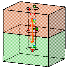
A symbol representing the Virtual Bolt Tightening Connection Property is visualized on the corresponding faces.

-
Optionally modify the default Tightening Force value.
-
Click OK in the Virtual Bolt Tightening Connection Property dialog box.
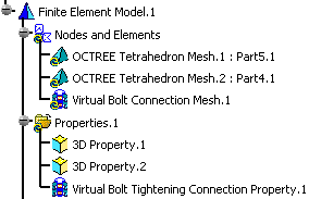
Note that two elements appear in the specification tree:
-
A Virtual Bolt Connection Mesh.1 connection mesh part under the Nodes and Elements set
-
A Virtual Bolt Tightening Connection Property.1 connection property under the Properties.1 set.

-
![]()