Open “…/online/ewrug_C2/samples/XMLrouting/Product1.CATProduct”
Make sure the CATIA options are properly set up: for the purpose of this scenario
- In
electrical mapping:
- Map the wire and wire group types
- Select ...\online\ewrug_C2\samples\XMLrouting\WireCatalog.catalog as electrical working catalog.
- In
external data interfacing:
- Enable the External System Interfacing
- Select ...\online\ewrug_C2\samples\XMLrouting as System Repository
-
Click Automatic Routing
 .
.The wire list opens with connectivity and attribute information: 
Note: Each wire group in the illustration contains one wire (indented to the right under the group).
For the wires and wire groups available in the list, you get the following information: - Name
- Type
- Identifier
- External diameter
- Bend radius
- Whether or not the wire or wire group is routed
- Whether or not the wire ends have been found, or changed.
Filters can help you make your selection:
- Hide already routed wires / wire groups
- Hide not routed wires / wire groups
- Hide wires whose ends are not found.
Routing options let you choose whether or not to use knowledge rules.
-
Select one or more wires and/or wire groups and click the right arrow.
The selected wires and wire groups shift to the right column: they will be routed. -
Select Check network to allow the system to automatically audit the harness, and solve the network connectivity issues.

Selecting this check box starts the network assistant and detects and fixes connection problems. -
Click Route.
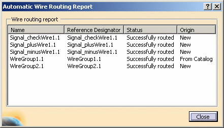
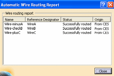
The Automatic Wire Routing Report is displayed. 
Since the routing now integrates the wire catalog: - If the wire or wire group is referenced in the catalog, the report indicates that the origin is From Catalog.
- If the wire or wire group is not referenced in the catalog, the report indicates that the origin is New.
- If
the Enable Sourcing access
option is selected in the Tools > Options
> Equipment & Systems >
Electrical Harness Discipline >
Electrical Assembly Design >
General tab, the Collaborative Enterprise Sourcing (CES)
environment is enabled. Under this circumstance:
- If the wire or wire group is referenced in the Sourcing Search dialog box, the report indicates that the origin is From CES.
- If the wire or wire group is not referenced in the catalog, the
report indicates that the origin is New.


For a given part number defined in iXFElec file, there must be one and only one part found after the query on ‘Internal Item Number’ criteria, else there would be an ambiguity.

Note that the specification tree icons also show that the first wire group is resolved; the other wire group and all wires are new. -
Close the report window.

- Selecting an individual wire in a wire group highlights the route of this wire.
- Selecting a wire group highlights the route of the entire group.
- A conflict may occur when using both Automatic Wire Routing and Automatic Equipotential Routing commands if the SignalId is valuated during wire routing.
- Automatic wire routing does not remove pre-existing routed wires even if they are not present in the loaded external iXF system.
Supported Devices/ Assemblies for Wire Routing
Only Assemblies connected through following connection points are supported:
-
Single insert connector and Shell should be connected via the cavity connection point of the connector and the cavity of the shell.
However, connection through cavity of the connector and cavity connection point of the shell is not supported for wire routing. -
Shell and Backshell should be connected through the connection points of the two devices.