To improve the highlight of the related geometry, see Highlighting of the Related Geometry for 3D Annotation.
Thread Creation using Thread Representation Creation
-
Right-click the PartBody and select PartBody object > Create Technological Results... to create the technological result node in the specification tree.
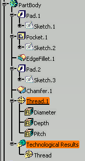
-
Click Thread Representation Creation
 in the
Geometry for 3D
Annotations toolbar.
in the
Geometry for 3D
Annotations toolbar.The Thread Representation Creation dialog box is displayed. 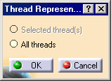
-
Select Thread from the Technological Results in the specification tree.
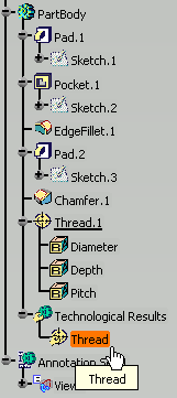
The Thread Representation Creation dialog box is updated to indicate that the thread representation will be created for the selected thread. 

In the case of numerous threads, selecting the All threads option lets you create the thread representations for all of them. If both the threaded hole feature (or thread feature) and the corresponding thread technological result feature are present in the document:
- For the Selected thread(s) option, if the cylindrical face (that is linked to the threaded hole feature or the thread feature and the corresponding thread technological result feature) is selected, the created thread construction geometry will be linked to the thread technological result feature.
- For the Selected thread(s) option, if the thread technological result feature is selected, the created thread construction geometry will be linked to it.
- For the Selected thread(s) option, if the threaded hole feature (or thread feature) is selected, the created thread construction geometry will be linked to the threaded hole feature (or the thread feature).
- For the All threads option, the created thread construction geometry will be linked to the thread technological result feature.
-
Click OK to validate and exit the dialog box.
The geometrical representation of the thread is displayed in the geometry. 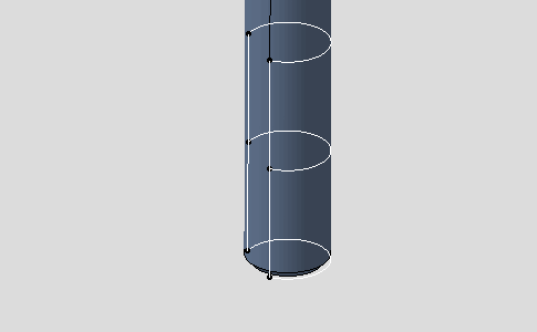
Thread Creation using Constructed Geometry Creation
-
Right-click the PartBody and select PartBody object > Create Technological Results... to create the technological result node in the specification tree.
-
Click Constructed Geometry Creation
 in
the
Geometry for 3D
Annotations toolbar.
 -
Select Thread from the Technological Results in the specification tree.
The Constructed Geometry Creation dialog box is displayed.- The Axis option allows you to create an axis construction geometry that will be linked to the cylindrical face.
- The Thread option allows you to create a thread construction geometry that will be linked in priority to the thread technological result feature.
Select the Thread option. 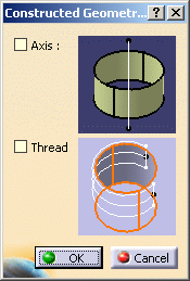
You can also select: - a threaded hole feature in the specification tree,
- a thread feature in the specification tree,
- the cylindrical face that is linked to either to a threaded hole feature, a thread feature or a thread technological feature in the 3D window.
If both the threaded hole feature (or thread feature) and the corresponding thread technological result feature are present in the document:
- If the cylindrical face (that is linked to the threaded hole feature or the thread feature and the corresponding thread technological result feature) is selected, the created thread construction geometry will be linked to the thread technological result feature.
- If the thread technological result feature is selected, the created thread construction geometry will be linked to it.
- If the threaded hole feature (or thread feature) is selected, the created thread construction geometry will be linked to the threaded hole feature (or the thread feature).
-
Click OK.
The geometrical representation of the thread is displayed in the geometry.

- If a threaded hole feature (or a thread feature) or its corresponding thread technological result feature or their corresponding cylindrical face is selected while the corresponding thread construction geometry has already been created, the Thread option is already selected in the Constructed Geometry dialog box.
- If the Thread option is cleared, the thread
construction geometry is deleted.
If the thread technological result feature to which the thread construction geometry is linked to, is deleted, then the thread construction geometry feature turns invalid even if the corresponding threaded hole feature (or a thread feature) has not been deleted.