 |
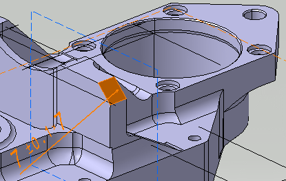
This task shows how to create dimensions and tolerances
for chamfer using the Tolerancing Advisor. |
 |
For a general introduction of the Tolerancing
Advisor, refer to Introducing the Tolerancing
Advisor. |
 |
Open the
Annotations_Part_02.CATPart document:
|
 |
-
Click Tolerancing Advisor
 in the Annotations toolbar.
-
The Semantic Tolerancing Advisor dialog box
appears.
-
Select the surface as shown on the part.
-
The Semantic Tolerancing Advisor dialog box is
updated according to the selected surface.
-
Click Chamfer Dimension
 . .
The Limit of Size Definition dialog box is displayed.
-
Enter the chamfer tolerance value and change the
parameters if required.
-
Click OK in the dialog box.
| The chamfer dimension is created. |
 |
-
Click Close in Semantic Tolerancing
Advisor dialog box.
|
 |
- Right-click the chamfer dimension and select Properties.
- To edit the tolerance values, select the Tolerance
tab.
 |
In the Tolerance tab, one more type of
Value Format, Angle X Distance is
available. Changing the dimension type to Angle X
Distance is not persistent. On editing or during
update of chamfer dimension, the format type is changed to
previous
Value Format. |
- To edit the values format values and representation, select the
Chamfer tab.
- Right-click the chamfer dimension and select Geometry
Connection Management. The Connection Management dialog
box displays the Group of Surfaces feature made up of three
user surface components. The first component is the chamfer face while
the other two components are the adjacent faces.
|
![]()