This task shows how to mesh spot welding connections.
You can mesh the following connections:
- Point Analysis Connection and Point Analysis Connection within one Part created in the Generative Structural Analysis workbench
- Joint created in the Body in White Fastening workbench (except for the joint created using the datum mode)
- Spot Welding Analysis Connection created before the V5R12
in the Analysis Connections workbench.
|
Connections |
Support |
|
Analysis Connections (from R12) |
One or two |
|
Body in White Fastener Connections |
One or more |
|
Analysis Connections (before R12) |
Two |
For more details about analysis connections, refer to the Generative Structural Analysis User's Guide - Analysis Connections.
For more details about joint containing hemming information, refer to the Automotive Body in White Fastening User's Guide - Creating Joint Bodies.
Open the sample27.CATAnalysis document from the samples directory.
-
Click Spot Welding Connection Mesh
 in the Welding Meshing Methods toolbar.
The Spot Welding Connection Mesh dialog box appears.
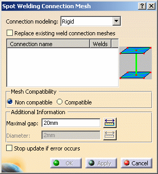
- Connection modeling:
Connection modeling
Non compatible mesh
Compatible mesh
- Beam


- Rigid
- Rigid-Spring-Rigid


- Spring-Rigid-Spring


- Hexahedron


- Replace existing weld connection meshes: allows you
to select a weld spot connection that has been already associated
to a mesh part.

You must activate this option before selecting the weld spot connection.
If not, a warning message informs you that the weld spot connection has been already meshed. - Mesh Compatibility:
- Non compatible: lets you create nodes by orthogonal projection of the welding points on the two mesh parts.
- Compatible: lets you use existing nodes.
The welding points must have been previously projected on the two mesh parts.
For more details, refer to Adding/Removing Constraints (Specifications).To know more about the recommended methodology to mesh seams using the Compatible mode, refer to Compatible Spot Mesh.
- Additional Information:
- Maximal gap: lets you specify the radius value of
a sphere which has the welding spot as center. It must be an
intersection between each face and the solid thus defined.
- The value must be strictly positive.
- While the Maximal gap value is null, the OK and the Apply buttons will be not available.
- If you update spot welding connections created before
the V5R12 level without modifying them, the data used to
mesh are the same as those used up to the V5R11 level.
Errors could be generated (for example: the maximal gap
value is too small).
In this case, you have to edit the connection mesh and to increase the Maximal Gap value.
- Diameter: lets you specify the diameter of the
hexahedron.
This option is only available if you selected the Hexahedron and the Non compatible options.
- Maximal gap: lets you specify the radius value of
a sphere which has the welding spot as center. It must be an
intersection between each face and the solid thus defined.
- Stop update if error occurs: lets you stop the
Update all meshes process.
If this option is activated and if you use the Update all meshes contextual menu, only the meshes created before the weld spot connection mesh will be updated.
- Connection modeling:
-
Select the connection you want to mesh in the specification tree.
In this particular example, select the Point Analysis Connection.1 object in the specification tree (under the Analysis Connections Manager.1 set).
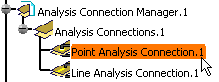
The Spot Welding Connection Mesh dialog box is updated.
-
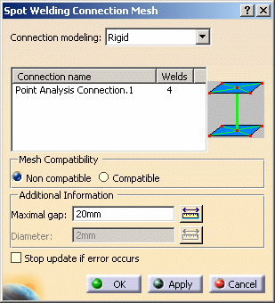
Set the desired parameters.
In this particular example:
-
Select Beam as Connection modeling option.
-
Select Non compatible as Mesh Compatibility option.
-
Enter 2mm as Maximal gap value.
-
-
Click Apply.
Several errors are displayed in the specification tree under the Spot Welding Connection Mesh.1 object.
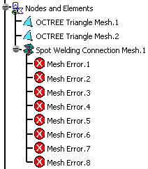
You have to change the Maximal gap value.
-
Enter 5mm as Maximal gap value.
-
Click Apply and then OK.
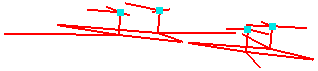
The connection mesh is now correct.

For a better visualization, you can change the mesh color using the Properties contextual menu.
You can also hide the OCTREE Triangle Mesh.1 and OCTREE Triangle Mesh.2 using the Hide/Show contextual menu:
-
Change the weld spot connection mesh parameters.
To do this, double-click the Spot Welding Connection Mesh.1 object in the specification tree to edit it.
The Spot Welding Connection Mesh dialog box appears.In this particular example:
-
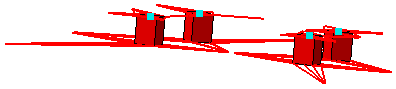
Select Hexahedron as Connection modeling option.
-
Enter 3mm as Diameter value.
-
Click Apply and then OK.
If you use the Hide/Show contextual menu to hide the OCTREE Triangle meshes, the result will be:
-