This task shows you how to project external curves to constrain them.
-
Open the Sample28.CATAnalysis document from the samples directory.
-
Enter the Surface Mesher workshop.
For more details, refer to Entering the Surface Mesher Workshop.
-
Click Project External Curve
 in the Local Specifications toolbar.
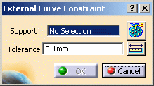
The External Curve Constraint dialog box appears:

- Support: lets you select the curves you want to
project.

Multi-selection of curves is available.
- Geometry Selector button
 :
for more details, refer to
Filtering Geometries.
 - Tolerance: lets you specify the tolerance value.
The Tools Palette toolbar also appears.
- Support: lets you select the curves you want to
project.
-
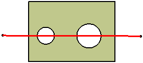
Select one or several geometric curves as Support.
In this particular example, select Geometrical Set.1 in the specification tree.
-
Enter a Tolerance value.
-
Click OK.
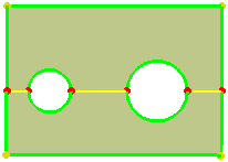
A Projected Curve.1 object belonging to Geometry Specifications.1 appears in the specification tree under the Surface Mesh.1 mesh part.

The selected curves are now yellow-highlighted and the points at the intersection of constrained curves are red-highlighted. They are constrained.


-
Click Mesh the Part
 to launch the mesh execution.
 -
Click OK in the Mesh the Part dialog box.
![]()