It can be a way to change locally the specifications of the part:
- by adding new specifications to a set of faces
- by changing a feature type
- by breaking feature dependency
For example, as shown in the first scenario, if you have a pattern of holes and want to edit only one or two holes out of it, then you can re-specify that hole with Part Rework. The new hole definition is available if you want to edit it.
Part Rework is shown in manual mode in this task but it is also available in local feature recognition mode.
Open the HolePattern.CATPart document.
-
Click the Manual Feature Recognition icon
 .
.
The Feature Recognition dialog box appears.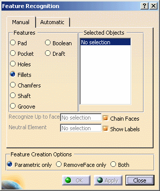
-
In this scenario we will break dependency of circular pattern of holes, so that one hole can be edited without affecting other holes in the pattern. To use Feature Recognition as Part Rework, just check the Both option at the bottom of the dialog.
Apart from isolated solid, Part Rework can also be used with any part design feature as In Work Object.
When any part design feature is in Work Object and not an isolated solid, then Feature Creation Options is by default set to Both i.e. for Part Rework mode.
-
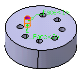
Check Hole in the dialog box and select the red face of the hole as shown:
-
Click OK to confirm the operation.
RemoveFace.1 and Hole.2 features are created as shown in the specification tree:
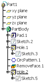
This newly defined holes can be edited without affecting other holes in the pattern.
Now, if you want to get original specification tree, you can easily get it by deleting RemoveFace.1 and Hole.2. Thus Part Rework ensures that you obtain desired results without changing original specification tree.
Breaking Face Continuity
Part Rework can even be used to break face continuity as illustrated in the example below. To perform the scenario, create a pad (from a rectangle including a corner) as shown here.
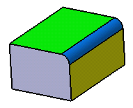
If you try to draft the yellow face, then the green face and blue fillet face will also get drafted with the same angle value, because of tangency. So if you want to draft these two faces with different angles, it is not possible with this specification tree, but Part Rework makes it possible.
-
Click the Manual Feature Recognition icon
 .
. -
First recognize the blue fillet. To do so, check Fillet in the dialog box and select the blue fillet.
-
Check the Both option at the bottom of the dialog.
-
Click OK to confirm the operation.
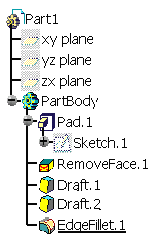
RemoveFace.1 and EdgeFillet.1 features are created as shown in the specification tree:
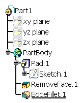
-
Now set RemoveFace.1 as In Work Object and then draft the two (yellow and green) faces with different angles as desired and then again set EdgeFillet.1 as In Work Object, you will obtain the desired results.
