 |
This task shows you
how to create a hanger. |
 |
Before you create
parts you should specify where they will be stored. A default directory is
specified but if you change it see
Understanding
Project Resource Management. The parts are normally moved from this
directory into the catalog. You should also create a graphic
representations file and specify where it is located. (See Defining
Directory Paths and Define Graphic
Representations for a Part.) See also
Definition of Hanger Attributes. If you want to be able to use the
same hanger in other V5 applications, such as Electrical Harness Discipline applications, as well as
other Equipment and Systems applications such as Piping and Tubing, then
it is recommended you do the following. It is important that you perform
them in the order described below.
- Create the hanger using the build process described in this task.
Assigning a type to the hanger first, using the Hanger Design workbench,
will allow you to use it in other disciplines.
- Add connectors as described in Creating
Connectors.
- Add electrical harness features such as type and entry/exit planes.
- Add the part to the Hanger Design catalog. You will now be able to
use the same hanger for Electrical Harness Discipline applications also.
You can also add the hanger to Electrical Harness Discipline catalogs.
|
|

|
1. |
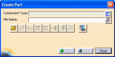
Click the Build Hanger Part
button  . The
Create Part
dialog box appears. . The
Create Part
dialog box appears.
 |
|
2. |
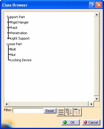
Click the Display Class
Browser button next to the Component Type field. The Class Browser
displays.
 |
|
3. |
The Class Browser allows you to
select the type of hanger you want to create. Navigate to the type you want
by clicking on the "plus" sign next to each directory, or by using the
three navigation buttons at the bottom. You can also filter for certain
types. For instance, you can enter "rack" in the Filter field and hit enter
to see all rack types. Click OK after making your selection.
After you click OK the Class Browser will close and the part you selected
will display in the Component Type field of the Create Part dialog box. |
|
4. |
The File Open button is used to
bring up a part, say, if you did not finish creating it and had to close
the application. Using the File Open button you can navigate to the
directory where the part is stored. |
|
5. |
The Define Properties button
 brings up the
Properties box, allowing you to change properties if needed. brings up the
Properties box, allowing you to change properties if needed.If you are
building a hanger that is to be placed on a run you must define the
Standard attribute. |
|
6. |
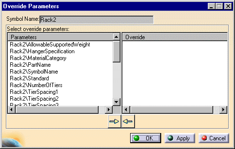
The Override Parameters button
 button brings up a dialog
box which allows you to override a parameter. When you click on a parameter
on the left side of the box and then click on the arrow to bring it on the
right side, that means the parameter can be overridden. (See
Change the Parameters of a Part.) When you
place this part the application will try to determine a value for that
parameter. If it cannot, then you will be asked to enter one. button brings up a dialog
box which allows you to override a parameter. When you click on a parameter
on the left side of the box and then click on the arrow to bring it on the
right side, that means the parameter can be overridden. (See
Change the Parameters of a Part.) When you
place this part the application will try to determine a value for that
parameter. If it cannot, then you will be asked to enter one.

|
|
7. |
Click the Design Table button
 to create a design
table and associate it to the part you are creating. For more information
on this see the Infrastructure document - Advanced Tasks - Using
Knowledgeware Capabilities. to create a design
table and associate it to the part you are creating. For more information
on this see the Infrastructure document - Advanced Tasks - Using
Knowledgeware Capabilities. |
|
8. |
Click the Formula button
 to create formulas and
parameters. See the Knowledgeware document mentioned above for more
information. to create formulas and
parameters. See the Knowledgeware document mentioned above for more
information. |
|
9. |
The Define Connectors button
 allows you to add
connectors. allows you to add
connectors. |
|
10. |
The Associate Attributes to Connectors button
 lets you
associate specifications to connectors. lets you
associate specifications to connectors. |
|
11. |
The Manage Representation button
 lets you
create and manage graphic representations. lets you
create and manage graphic representations. |
| |
12. |
The Set Object Type button
 can be used to
set the object
type. can be used to
set the object
type. |
|
13. |
Click the Use ID Schema button
 next to the
File Name
field if you want the application to generate a name for the part. next to the
File Name
field if you want the application to generate a name for the part. |
|
14. |
Enter a name for the part in the Symbol Name
field and press Enter. Click Apply or OK. The
part is created. In the illustration below it has been named Rack2.

The part has been created but it still does not have a graphic
representation - it has no "looks". You will learn how to create one or
more graphic representations for the part in subsequent tasks. |
|
15. |
You must save the part to the
directory specified in your Options dialog box. Double-click on the part
Rack2 (in the image above) to make it active, and then use the File
menu to save it. |
|
 |
![]()


![]()