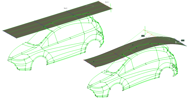
An automatically created reference is always a surface. Its position an alignment can be defined. The automatically created reference is updated if additional geometry is selected.
The following combinations are available for modeling shapes:
-
Click the Shape Modeling icon:

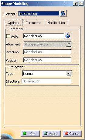
The Shape Modeling dialog box is displayed.
-
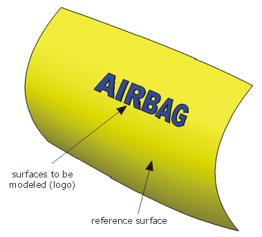
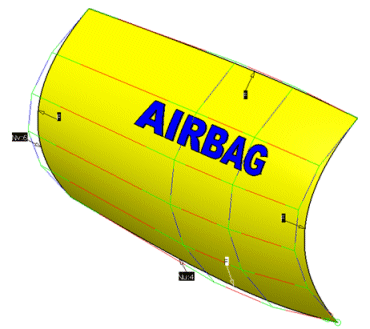
Select the 68 surfaces of the Airbag logo to be modeled.
Terminate the selection with F8. -
Select the reference surface.
Terminate the selection with F8.
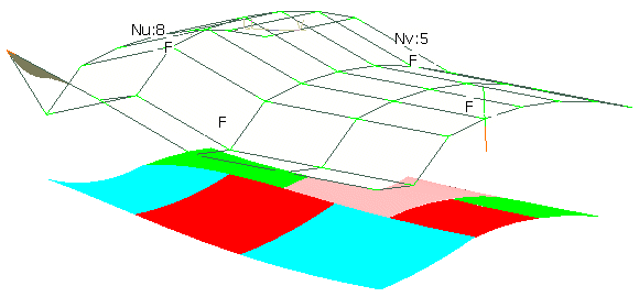
The control points are shown.
-
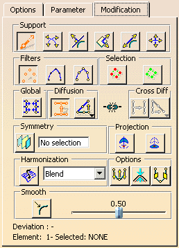
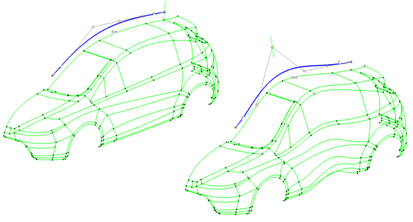
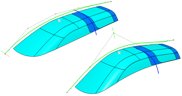
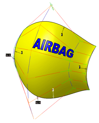
Switch to the 'Modification' tab and modify the reference surface.
The result of the shape modeling is a datum.
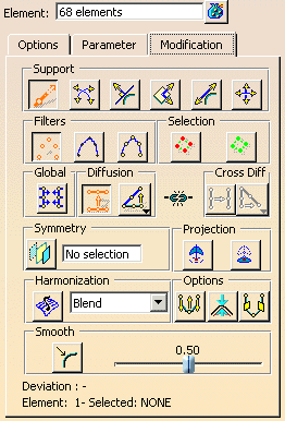
- Element: Selection of the geometry elements to be modeled.
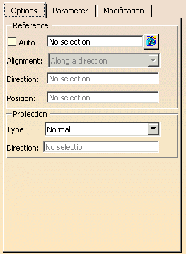
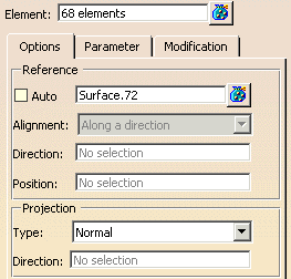
- Reference: Definition of the reference.
- Auto:
- OFF: Selection of reference elements.
- ON: Automatic creation of the reference surface.
Note: Automatically created reference surfaces are transparent. For a good transparency display, activate the option Transparency Quality: High in the menu Tools > Options > General > Dsiplay > Performance.
The options 'Alignment', 'Direction', and 'Position' are available for the automatic creation of a reference surface ('Auto' ON).
- Alignment: Alignment of the automatically created reference surface.
- Normal: The reference is perpendicular to the surface normal and runs through the point of surface defined in the field Position.
- Along a Direction: The reference is perpendicular to the vector defined at Direction and runs through the point defined in the field Position.
- Auto:
- Projection: The selected elements are projected on the reference in the defined direction. Generally, the projection
is selected in a way that all elements meet the reference.
- Type: Projection direction.
- Normal: The elements are projected on the reference in the direction of its surface normals.
- Along a Direction: The elements are projected on the reference in the direction of the vector defined in the field Direction.
- Type: Projection direction.
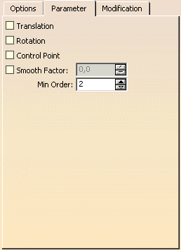
To activate the options on this tab, you have always to click on the button 'Apply' after switching on an option.
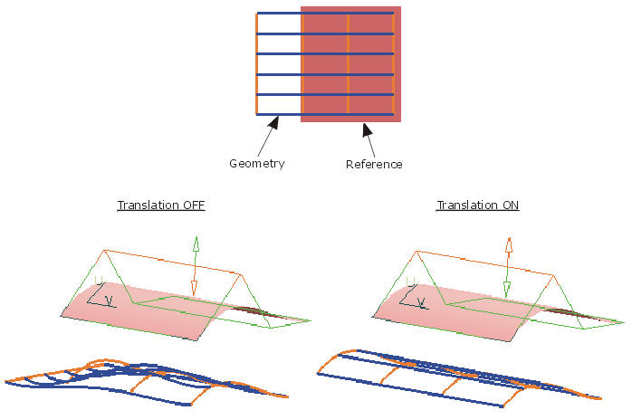
- Translation: The reference should cover the geometry elements. An automatically created
reference always covers all geometry elements.
The covered region of the geometry elements is modified like the corresponding region of the reference.
With the option 'Translation', you may determine how geometry regions which are not covered by the reference shall behave during the modification.- OFF: The non-covered regions will not be translated like the covered region, but can be influenced by the modification of the covered region (stretched or compressed).
- ON: The non-covered regions will be translated like the covered region.
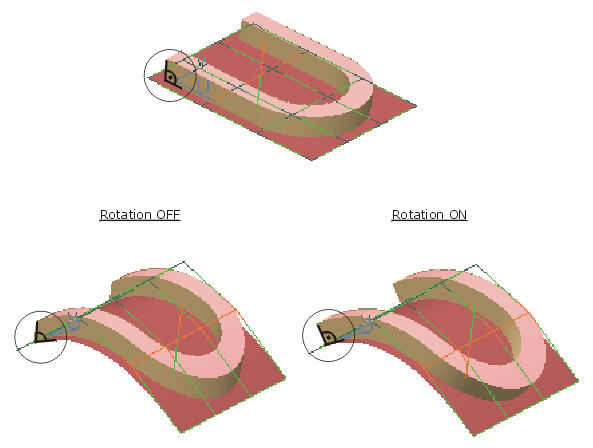
- Rotation: This option has only influence on surfaces as selected geometry elements. You may determine whether
the geometry shall be rotated according to the reference during the modification or not.
- OFF: The geometry will only be translated.
- ON: The geometry will be rotated additionally. The angle between geometry and reference will be kept.
- Control Point: With this option you may define, whether the geometry or the control points of the selected geometry
elements will be modified.
- OFF: The geometry will be modified.
- ON: The control points will be modified..
- Smooth Factor: Smoothing for the approximation.
- OFF: A smooth factor of 0 is used (no smoothing).
- ON: The smooth factor can be specified.
- Min. Order: If the selected geometry elements have a lower order than the minimum order specified here, their order will automatically be increased to this value.
