-
Click the Overcrowning icon
 .
.
The 'Overcrowning' dialog box is displayed.

-
Select Surface.1 as the Element.
Note: Pick F8 to confirm selection or pick inside an input field. You can also pre-select the surface before clicking onto the Overcrowning icon. -
Change Crowning height to be 50 mm.
-
Turn on Scaling.
-
Set Edge tolerance on the Advanced tab to 0.1
-
Select a point on the geometry. At this position, the vector is placed having a length equal to the Crowning value. The crowning value and direction can be modified dynamically using the vector symbol.
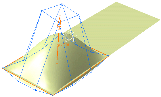
-
Change the Scaling to 2, and Min. Order to 4, then Edge Continuity to Tangent and Curvature, and observe the differences.
You can define the following options:
- Element: Specifies the elements to overcrown.
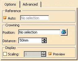
- Reference: The parameters of the crowning function can either be applied to an automatically computed reference patch (Auto ON) or a selected reference patch (Auto OFF and selection).
- Crowning
- Position: Definition of point positions for the overcrown vectors.
- Distance: Crowning value. The vectors placed at the crowning positions have a length equal to this value.
- Display
- Scaling: Scaling factor for the display of the vectors.
- Preview: Preview on the reference patch during the modification.
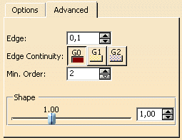
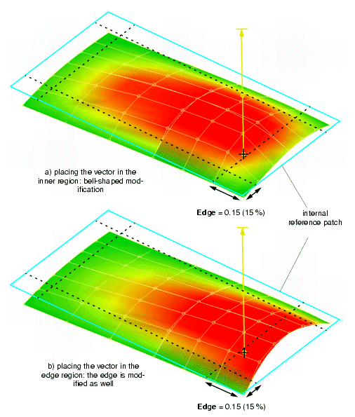
- Edge: This value determines which region of the reference surface is considered to be the
edge. This is illustrated in the following figure:
A value of 0.15 means that the inner region is 15 % away from the outer edge of the reference surface. Placing the vector in the inner region results in a bell-shaped modification (a).
If the vector is placed in the edge region, the corresponding edge is modified as well (b).
- Edge Continuity: The required edge continuity of the underlying reference surface
can be set with this popup menu.
Note: Setting the edge continuity only applies to the reference patch used for the computation.
- Min Order: The minimum order of the selected elements can be determined.
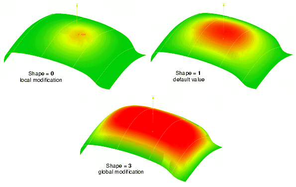
- Shape: The shape of the crowning can subsequently be modified. A small value causes a local and a large value a global modification. The crowning value is kept constant during this modeling. The default setting of the shape value is 1, since with this value an optimum control point distribution can be achieved.
![]()