This task describes how to check surfaces.
The ISD Surface Checker command is used to check sets of surfaces regarding their Class-A quality using user-defined parameters before releasing them for downstream processing.
-
Click the Surface Checker icon
 .
.
The 'Surface Checker' dialog box is displayed.
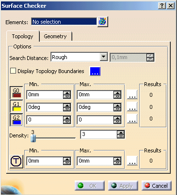
The following options can be defined:
- Element: Selection of the surface geometry to be analyzed .
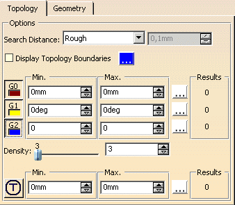
- Search Distance: All surfaces with a distance from each other which is smaller than specified tolerance are searched
for. These surfaces are neighbored building up a topology region. These regions can be displayed graphically with the check
button. For getting neighborhood information for surfaces, the Search Distance within the specified tolerance are always searched
for at first, also with deactivated option. All checks are calculated within these regions. If no Search Distance can be found,
all the other activated checks will produce no result. You will only get a check result for the position continuity, for example,
if the tolerance value for Search Distance is larger than the minimum tolerance value for position.
- Rough: The Search Distance is pre-set to 0,1mm.
- Fine: The Search Distance is pre-set to the CATIA V5 tolerance of 0,001mm.
- User: The Search Distance numerical field is available to allow the user to specify a value.
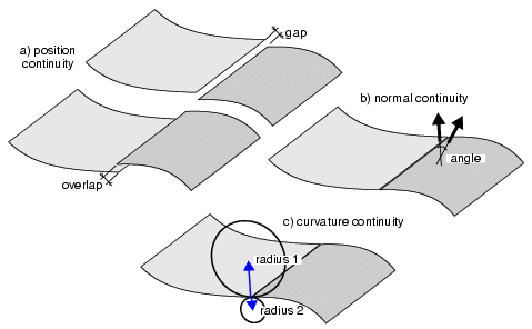
- G0, G1, G2:The Surface edges within the Search Distance will be checked for position, normal and curvature continuity. By default, continuity button is turned off. Only when the button is selected (depressed) will the Topology analysis type be performed.
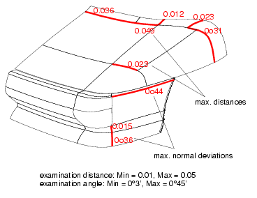
Display of the checking results regarding G0 and G1 continuity
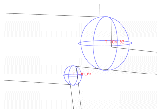
- T:With this option, all T-connections in patch clusters are marked, where the misalignment between the corner
points lies within the tolerance range specified.
The regions where a misalignment between the selected topologically contiguous surfaces is diagnosed are displayed in the graphic area as blue spheres. Each misalignment region is named with the prefix 'T_CON' and a consecutive number.
By default, T-Connection button is turned off. Only when the button is selected (depressed) will the Topology analysis type be performed.

Note: Please note that users should specify values for the tolerance range that are falling considerably below the dimensions of the surfaces to be checked. If edge lengths of checked surfaces are lying within the tolerance range, these edges are output as T-connection. This result may be undesirable.
- Min, Max: The edges at which the current distance, angle or curvature lies within the specified range (specification
of values for Min, Max) will be marked. The maximum values will be indicated.
- Density: A user defined value which determines the number of points at which the position, normal or curvature
continuity is to be checked along the edges of the selected elements. Users can use the slider bar to increase/decrease the
value.
- Color: The user can specify the color of the Topology condition to help identify graphically the local condition.
- Results: The Results field display the number of topology connections found for individual options.
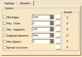
- Mini Edges: All edges with a shorter length are marked.
- Max. Order: All elements with a higher order are marked.
- Max. Segments: All objects with a larger number of segments are marked.
- Duplicate Elements: All duplicate objects are marked. Objects with identical edges lying on top of each other are recognized.
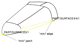
- Mini Objects: All objects with a smaller surface area are marked.
Mini objects and mini edges
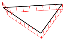
- Normal Turn Down: Irregularities of the normals can be found with this option.
Normal turndown in a triangular patch
![]()