The user can dynamically interact with manipulators
to define the end points of the blend curve.
Transition constraints can be defined (G0-G2).
In addition, in case of G1 or G2, tangent lengths can be controlled by arrow manipulators. Clicking on the tool's peak changes
the direction of the tangent.
-
Click the Blend Curves icon
 .
.
The 'Blend Curve' dialog box opens.

-
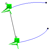
Click on one end of each curve and click Apply.
The Blend Curve and UI-Tools appear.
-
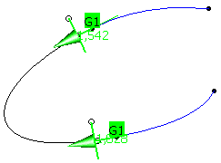
Set the continuity to G1
-
If you pull on handle at the end of the manipulator, you can vary the radius of the blend curve.

-
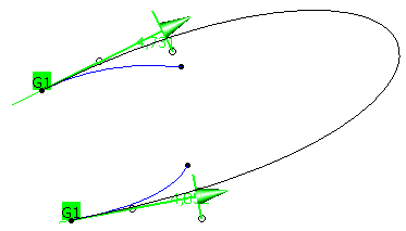
With a click on the other middle handle of the manipulator you swap the direction of the tangent.
-
Click OK to create the blend curve.
- Curve 1,Curve 2: Selection of the two curve end points can be carried out between which the blend curve is to be generated.
 Trim: The original curves will be trimmed at the end points
of the connecting curve.
Trim: The original curves will be trimmed at the end points
of the connecting curve.- Curve 1 options, Curve 2 options
- Continuity: The continuity conditions can be defined before creating the blend curve. Default setting is G1.
 Link: The continuity conditions of both curves can
be linked.
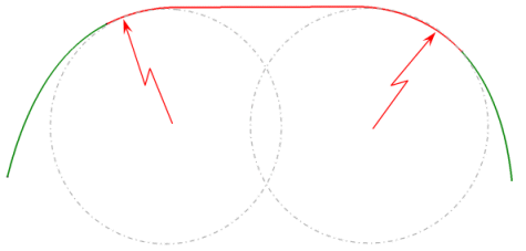
| Start Radius: Definition of a radius at the appropriate curve end. This option can only be activated for continuity
G2. If a radius is specified, the manipulator at the appropriate curve end is no longer available. Depending on the users choice of options, the segmentation of the result curve will change: no radius value set > 1-segment curve 1 radius value set > 2-segment curve 2 radius values set > 3-segment curve |
|
| Invert: Inverts the radius by using the negative value. |

| Mid Continuity: Continuity condition for the middle part of the connecting curve when a radius is defined. This option is only available if 'Start Radius' is switched on. |
|
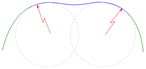
| Direction: The tangent and curvature continuity can be adopted from any other curve. The position is adopted from the adjacent curve in either case. In the case of a matching between Curve 1 and Curve 2 where a clear direction is not determined, you can define a direction via this selection field or the contextual menu. | |
| Limit: A new start point can be defined by selecting a point or curve. |
![]()