You have to select two input sets of surfaces. A rolling ball runs between the selected input sets. The radius
of this rolling ball is the fillet radius. It marks a curve on each surface.
An option is to select a curve on the first input set and the other input set. This curve and the other input set define the
radius of the rolling ball. This ball has to touch the input set on this curve and creates a curve on the other input set.
These curves have to be 2D-Curves and have to begin on one edge of the surface and to end on the other edge of the surface.
The fillet surface is created between these two curves. The fillet surface is not created in all options by this rolling ball.
The radius of this ball can change while moving.
For using variable fillet, the two surfaces must have a common edge inside the given 'edge tolerance', otherwise
variable is inactive.
Vector tools defining the radius values are displayed. The color of the tools is depending on the success of the function,
which is red if no fillet has been created.
For variable fillet initially two vector tools are displayed on the common edge. For more complex fillet laws an arbitrary
number of tools may be inserted.
The length of each vector tool and the position of the inner tools can be modified and the fillet is recomputed dynamically.
As many fillet commands as desired can be defined for working in parallel.
Feature modeling of the fillet surface is possible. Caution: the given radii may be violated.
Deviation feedback is available.
-
Click the Styling Fillet icon
 .
.
The Styling Fillet dialog box is displayed.

-
Select the two surfaces where you want to create the fillet.
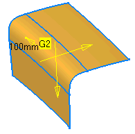
Two vectors and the continuity symbol appears (G2).

-
Click Apply to create the fillet. This option is only available for G2 and not for G0 or G1.

When you activate minimum radius, a new vector appears enabling you to change the minimum radius in the middle of the fillet. Alternatively, you can change the value using the up and down arrows in the Minimum Radius.

- Support 1 / Support 2: Selection of Surfaces and Curves as input sets. There are 6 combinations possible:
- 2 sets of surfaces
- 2 sets of curves
- (1 set of surfaces + 1 set of curves on these surfaces) + (1 set of surfaces + 1 set de curves on these surfaces)
- (1 set of surfaces + 1 set de curves on these surfaces) + (1 set of surfaces)
- (1 set of surfaces + 1 set de curves on these surfaces) + (1 set of curves)
- (1 set of surfaces ) + (1 set of curves)

- Continuity: You can specify the order of continuity between fillet and reference surfaces (G0, G1 and G2). In case of G0 continuity, it is not relevant to call this option a G0 fillet, but it is useful in some cases to be able to access this functionality without changing command.
- Spine, Point (in ISD only): In the case of fillet between two surfacic elements with a spine, you will be able to select a point on the previously selected spine.
- Radius Parameters
- Radius: Fillet radius.
- Min Radius: Minimum radius in the middle of the fillet (optional). This option is available only for G2 continuity mode and is not compatible with True Minimum option.
Example: You have a fillet surface with Variable Radius R=60 and r=40. The Minimum Radius is 20. 20mm is the Minimum Radius of the Fillet Surface at the point where the Radius is r=40. The Quotient q is: q=r/20=2. The Minimum Radius of the fillet surface at the point where the radius is R=60 is R/q=60/2=30. |
- Arc Type: This option influences the fillet surface only in fillet direction
and available only for G1 continuity mode. Providing this option creates a fillet with specific order and segmentation as
follows.
 Blend (in ISD only): Creates a blend surface
between; order 4, segment 1.
 Approx: Creates a circular bezier approximation;
order 6, segment 1.
 Exact: Creates a rational surface with true circular
sections; order 3, segment 1.
Arc type 'Exact' means that the arc of circle is an exact representation with a rational BSpline curve. Consequently, the created surface is a polynomial surface with 'Approx' option and it is a rational BSpline surface with 'Exact' option.
- Fillet Type
 Variable Radius: Activates variable
radius (only possible if edge tolerance is met). A UI-Tool (vector) appears at each end of the fillet surface with which
you can modify the radius at each end individually. Additional ones can be created with the manipulator in the middle
of the fillet surface.
 Chordal Fillet (only for 'Variable Radius'
off): The distance between the edges of the fillet in direction of the rolling ball is the chordal distance. The chordal
distance is kept constant.
 True Minimum: This option is available
only with the G2 continuity and controls the minimum radius. Trace curves are computed depending on G2. The option is
not available when the Min Radius option is selected. But the value for the minimum radius is available and
acts as the value for true minimum option.
- Result
- Geometry

 Extrapolate Side 1, Extrapolate Side 2: Fillet surface also on extrapolation of
reference surfaces.
 Relimit Side 1, Relimit Side 2 (Only active if 'Extrapolate Side 1' or 'Extrapolate Side 2'
is ON): The fillet surface can be trimmed in two different ways. The fillet surface is the basic surface for the trim
operation.
 Trim Face: The basic surface remains
unchanged.
 Trim Approx: The basic surface changes.
The result is not a face.
 Merge (in ISD only): This option is
only of interest if the fillet surface results in more than one surface. These surfaces can be joined and the result
is one surface. Join is only possible if the translation condition between the surfaces allows to join then with G2-Continuity.
- Simplification (in ISD only): If both input sets have more than one surface and the boundaries of
the surfaces are not exactly on the same position, the result is a (very) small surface.
 Small Surface - Stitch: The small surface
can be stitched with one of the neighbor surfaces. It is not the hand of the user to select this neighbor surface.
The small surface looks to which of its neighbor surfaces it fits better.
 Small Surface - Rip: The small surface is (along
its diagonal) divided into two surfaces. Each port is joined its boundary surface.
- Geometry
- Deviation Display: Displays the deviations in the 3D area for the local connect checker in the fillet. In the
3D, the deviations are displayed for locations where the continuities are inferior or equal to the selected level of continuity.
In case you have selected G1 for fillet construction, maximum deviations for G0 and G1
locations are displayed, but maximum deviation for G2 is not displayed.
- Connection Between Fillet Cells
 : Click this button
to display or hide the deviation values (within the fillet result) in the 3D area. This option analyzes only the ribbon.
If one of the Trim Support option is On, the result fillet contains ribbon and the trimmed support. In this case the option analyses only the ribbon from the result fillet. - Connection Between Fillet ribbon and Support
 : Click this button to
display or hide the deviation values (between the fillet result and its support) in the 3D area.
If one of the Trim Support option is On, the supports are consumed by the result fillet. In this case the option analyses connections between ribbon and the trimmed supports. If both the trim options are On, the supports are consumed by the fillet and thus connection analysis is not done between the fillet and support.
- Connection Between Fillet Cells
- Max Deviation: In this area the maximum deviations values of all the applicable continuity are displayed along
with their units.
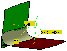
Click Connection Between Fillet ribbon and Support button and click Apply. You can see that the G2 value is displayed in the 3D area. G0 and G1 are not displayed in 3D area as their values are equal to 0.
- The deviation values are displayed in the 3D area only till the Styling Fillet command is active. After clicking OK in the Styling Fillet dialog box the values disappear.
- The deviation values are updated when the fillet gets updated.
- The following continuity value tolerances are defined:
- G0: 0.001 mm
- G1: 0.01 degree
- G2: 2%.
Continuities having values below these tolerances are considered as zero.

- Options
- No Approximation:
- Automatic:
- Limited:
 Tolerance (in ISD only):
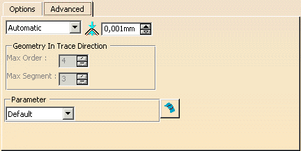
- Geometry in Trace Direction (in ISD only, only for 'Automatic' and 'Limited')
- Max. Order: Maximum order of the surface in direction of the rolling ball.
- Max. Segments: Maximum number of segments for the fillet surface in direction of the rolling ball.
- Parameter: Different options for parameterization of the result and fillet surface.
- Default: Internal computed best filling parameterization.
- Patch 1: Parameterization is taken from the 1st patch. For Advanced mode, one Patch 1 is available.
- Patch 2: Parameterization is taken from the 2nd patch.
- Average: Average of parameterization from patch 1 and patch 2 is taken.
- Blend: Traces have parameterization of their correspondent surface.
- Chordal: The parameterization is the chordal parameterization.
 Independent Approximation: Independent internal
approximation. The parameterization of one fillet surface is calculated disregarding the parameterization of the neighboring
fillet surfaces. The interest of this option is the approximations are independent face by face, so a “bad” control points
mesh on a face could not influence the other faces if this option is enabled.
![]()

