To allow the definition of the type of geometry output structure required, the Output tab offers two main options:
- Multi-single-segmented-cells (Bézier) and
- Single-multi-segmented-cell (Single B-Spline)
In addition to the type of output required, the amount of cells (patches/curves) can be reduced via a tolerance.
| General rule: The Output tab options are entirely a user choice. If not used the command will create a result depending upon the inputs and approximation settings. |
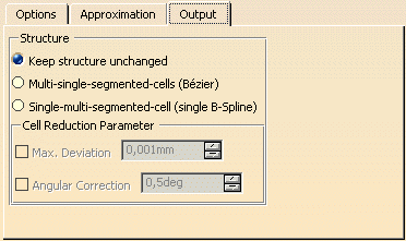
- Keep structure unchanged: The result will be created depending upon the inputs and approximation settings.
- Multi-single-segmented-cells (Bézier) (default): The output will be defined to be Bézier results.
Advantages: Individual cells (Bézier) can be created between each segment boundary which is determined by the input geometry and the settings from the Approximation tab. Each cell is G1 continuous to the adjacent cell - Single-multi-segmented-cell (Single B-Spline): The output will be defined to be B-Spline results.
When activated the result output is aimed towards reducing the amount of cells (patches or curves) but each cell can be a multi-segmented result (B-Spline).
Advantages:
Individual cells are created of which each cell can contain a multi-segmented result. The number of segments per cell is determined by the input geometry and the settings from the Approximation tab.
Each multi-segmented cell is internally G2 continuous with each cell being G1 continuous to the adjacent cell. - Cell Reduction Parameter: The result produced can be reduced via a tolerance value according to a continuity
condition.
- Max. Deviation: When on you can enter a value which allows the output to deviate from the original result according to either the Tangent or Curvature options. The higher the value, the less cells are created.
- Angular Correction: The output result is analyzed for tangent and curvature continuity.
Options are made available to allow you to perform a tangency or curvature smoothing of any discontinuities found on the projected curve result. You can only select an element, not a sub-element, as the curve to be smoothed.
The amount of deviation allowed during the selection of tangency or curvature is controlled via the 'Max. Deviation' value.
The criteria for what is allowable tangency and curvature conditions are defined using the Topology tab in Tools > Options > ICEM Shape Design.
- Multi-Result:
These options are only available on the Output tab of the command
Create Gap
If several input elements have been selected, you can select the following options for the result:- Multi-Result without Topology Check: A result is created for each selected element.
- Single-Result with Topology Check: Topologically contiguous elements are connected to a join, and for each join is created a result.
- Single-Result without Topology Check: For all selected elements is created a result, each element being calculated individually.