Open the MultiSelection.CATPart document.
-
Click Modification
 in the Modification toolbar.
 -
Select Subdivision Surface.1.
-
Click Multi-Selection
 .
.
You can also access this command by pressing CTRL+SPACE. -
Press Crtl key and select Subdivision Surface.3.
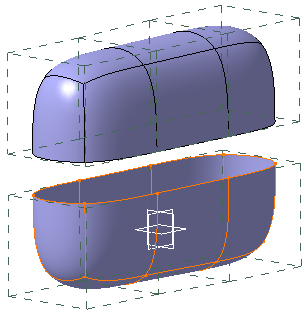
-
Click Multi Selection
 and
you are back to Modification
 command.
- In case
of multiple selection of subdivision surfaces, each subdivision mesh
is displayed in a different color for easier
identification.

- To display the meshes in same default color, clear the
check box Automatic colored in Multi-Selection Mode in
Tools > Options > Shape > Imagine & Shape > Display tab.
The default color is as specified in
Tools > Options > General > Display > Visualization
tab, Color area.
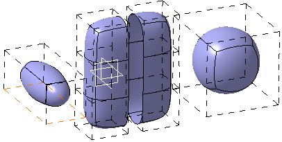
- There is no set rule for the order of colors to be displayed. If you deselect or reselect a subdivision, its color may change.
- Selected elements are displayed in red color and the pre-selected elements in orange as the previous behavior and these colors are kept for the elements in all the meshes.
Modification of Multiple Surfaces
-
Select the faces on these two subdivision surfaces. You can use the Ctrl key to multi-select the faces. You can add, remove and change the selected faces.
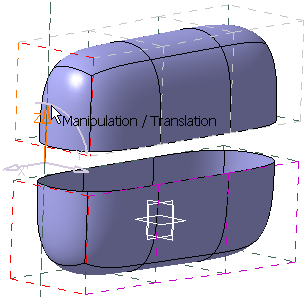
The All Elements Selection
 will select all the faces of the two subdivision surface.
 -
Click Translation
 .
. -
Move the mouse cursor to highlight the desired axis or plane.
-
Hold down the left-mouse button and drag to translate the surfaces.
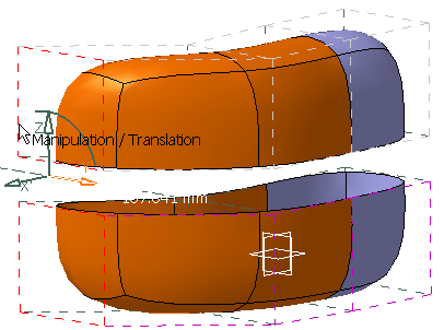
-
Release the left-mouse button when you are satisfied with the new position of the surfaces.
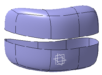
Use One Subdivision Surface to Modify Another
-
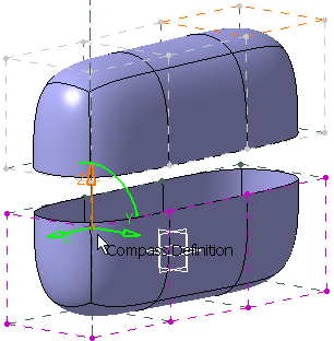
Click Compass Definition
 to define the compass' position on Subdivision Surface.3.
-
Click Compass Definition
 again.
 -
Click Alignment
 .
. -
Select the multiple edges or vertices on Subdivision Surface.1 to align them on Subdivision Surface.3. You can use the Ctrl key to multi-select the vertices. You can add, remove and change the selected vertices.
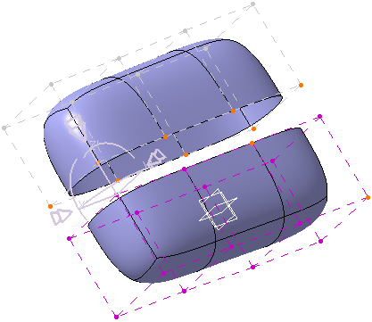
-
Click the manipulator to project the edges.
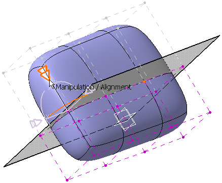
You can see that the edges are projected.
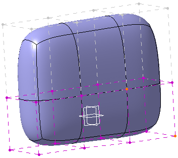
The result is: 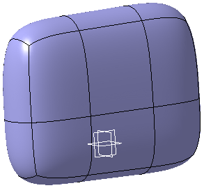
- All modification commands can be applied to multiple surfaces.
- When you work with more than a one subdivision surface, if the working zone option is activated (or deactivated); it will be activated (or deactivated) for the entire selected subdivision surfaces. For more information on working zone, refer to Defining The Working Zone.
- If you have selected the faces or edges or vertices of a subdivision, and further deselected the subdivision, then reselecting this subdivision will highlight all previously selected elements.
Smart Selection of Multiple Surfaces
Open the SmartSelection.CATPart document.
-
Select
EdgeFillet.1 and click Modification
 to modify it.
You can see that all the parent subdivision surfaces are highlighted in
the specification tree. The Tools Palette
also appears.
 -
Press
Ctrl
key and select the parent subdivision surfaces you want to modify.
In this case select two subdivision surfaces. -
Click
End Selection
 in the Tools Palette
to validate the selection.
You can see that the selected subdivision surfaces can now be modified.

![]()