contained in a DXF file into a CATDrawing document.
Once imported, the data can be handled and edited just as if they had been created
in a Drafting session using 2D geometry creation commands.
The table entitled What about the elements you import ? provides information on the entities you can import.
You can find further information in the Advanced Tasks:
- Trouble Shooting,
- Best Practices,
- FAQ,
- VBScript Macros
- and in the Customizing DXF/DWG Settings chapter.
Statistics about each import operation can be found in the report file created.
-
To import an existing DXF/DWG file, select the File > Open items or
To insert a DXF/DWG file in an existing CATDrawing document, select the Tools > Import From File.
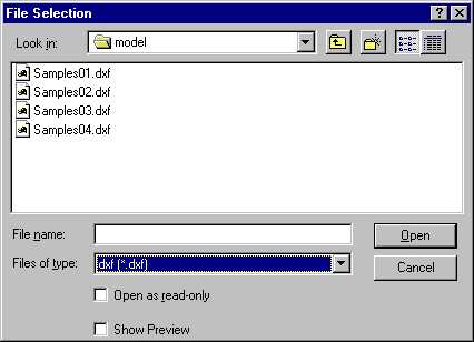
The File Selection dialog box is displayed:
-
Select the .dxf/.dwg extension from the field called Files of type.
All .dxf/.dwg files contained in the selected directory are now displayed. -
Click the .dxf/.dwg file of your choice.
-
Click Open.
- In import mode, a CATDrawing is created in session which contains all the geometry converted from the DXF/DWG file. This CATDrawing becomes the current document.
- In insertion mode, the geometry of the DXF/DWG file is created in the current drawing.
Import of multiple viewports and layouts
If the model
is referenced, at least partially,
by one or several viewports, the model is not created in a sheet of its own.
Only layouts are created.
They will contain eventual viewports.
In this case, select the option
Keep model space to force the creation of the model space in its
own sheet.
V5 does not create empty viewports or layouts.
In insertion mode, the first layout (or the model space) is inserted in the current sheet but it cannot be inserted in a detail sheet: if the current sheet is a detail sheet, new sheets are created.
Format
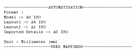
V5 determines systematically and automatically the most suitable format
(A0 ISO, A1 ISO, etc.)
for each sheet (layout) i.e. V5 chooses the smallest format in which the
drawing can be totally included, in conjunction with the unit either chosen
or automatically computed depending on the import options:
- If the standard is ISO, V5 chooses the format among A0, A1, A2, etc.
- If the standard is ANSI, V5 chooses the format among A, B, C, etc.
- If no standard format fits the sheet, the format is set to the largest
one i.e. A0 ISO and
made invisible with a message "No standard format can be applied to this sheet" in the report file. - If you are not satisfied with this automatic result, use the Page Setup command to modify the format.
- The resulting views are automatically centered in the sheet and take the format into account.
Information on what has been determined automatically is written in the report file:

For more information on Formats,
see the Defining a Sheet chapter in the Generative Drafting User's Guide.
In insertion mode, when new views are inserted in the current sheet, this sheet will take the name of the corresponding DXF/DWG layout and the format of the sheet will be modified. So it is recommended to insert DXF/DWG files in a new sheet.
Code pages
DBCS (Double Byte Character Set) Supported Code Pages are:
- 932 (Japanese)
- 936 (Simplified Chinese)
- 950 (Traditional Chinese)
Customization
Import of a DXF/DWG file can be improved by customization:
DXF/DWG specific import settings are:
-
Standards. The lists of attributes are not the same in V5 and AutoCAD.
A DXF mapping standard file is used to come as close as possible to the AutoCAD attributes,
or to switch them to V5 attributes. - Unit of the file
The definitions of dimensions are not the same in V5 and AutoCAD.
This option is used to give priority either to the graphic closeness or to
the re-usability in V5.
![]()