![]()
DMU Kinematics Simulator lets you easily edit joints. Editing joints means you can modify:
-
its name
-
deactivate the command if any
-
modify its specifications (curve joints specifications: point curve, slide curve, roll curve joints)
either editing the existing geometry joint or replacing the existing geometry with a new one. Inboth cases, the mechanism is updated accordingly. Read Editing Curve Joints - Introduction
![]()
This task shows you how to edit joints
![]()
Open the rods+4joints.CATProduct document.
-
Double-click the joint. In our example: Revolute.1.
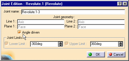
The Joint Edition: Revolute 1 dialog box appears.
The parts which are not involved in this joint are low-lighted.
-
Name the joint: Revolute. 1-3 for example.

-
To assign an angle driven command, select the Angle driven check box .

You can check the command positive orientation and invert it if necessary (either during joint or command edition). Note though, for Roll curve and Point curve joints you can only check the command orientation but not change it.
The command orientation is defined by a green arrow (or or a blue arrow when it is possible todetermine the absolute movement of the sense of motion ) in the geometry area
-
The parts which are not involved in the joint creation are displayed in low light (to easily locate the joint you are working on):
-
Pass the cursor over the green arrow or blue arrow to launch a short animation
-
Click the arrow to reverse the command orientation if necessary

The positive orientation of a command indicates the absolute movement of the parts involved (in the joint which is assigned the command) if it is possible (for open chain mechanisms) if not it indicates the relative sense of motion (intrinsic movement of the second part with respect to the first part involved in the joint).
-
-
Set joints limits if needed.
See Setting Joint Limits and Checking Joint Limits. -
Click OK.
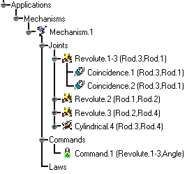
The revolute joint is updated and identified in the specification under its new name.
The angle command assigned to Revolute.1-3 is also identified.
![]()