Automatic switch to Design mode:
If you work with the cache system in visualization mode, you no longer need to use Edit > Representations > Design Mode beforehand as the switch to design mode is automatic (an eye appears as you point the product in the geometry or specification tree). All you need to do is click on the object.
-
Click Cylindrical Joint
 .
.
The Joint Creation: Cylindrical dialog box appears -
Click New Mechanism. The Mechanism Creation dialog box is displayed:

In our example, keep the default name Mechanism.1.
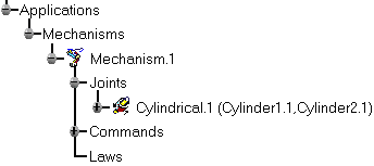
The Mechanism is identified in the specification tree.
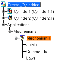
Now you need to select two lines
-
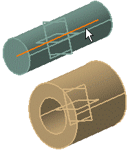
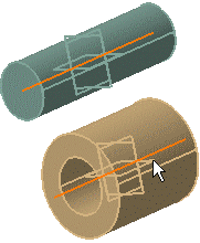
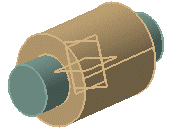
Select Line 1 in the geometry area. In our example select the Cylinder 1 axis
-
Select Line 2 in the geometry area. Select the Cylinder 2 axis
-
Select the Angle driven and Length driven check boxes
-
Click Ok.
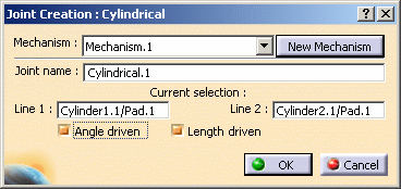
The joint is created and identified in the specification tree
-
Define a Fixed part, for this click Fixed Part
 and select the object (Cylinder 2).
The mechanism can be simulated. -
Open the Create_Cylindrical_Result.CATProduct document to check your result.