At this stage, you may want to maximize the 2D window. You will not be working in the 3D window for the moment, so you do not need to have it displayed all the time.
Configuring your options |
|
|
|
For more information on the various options available in the Visualization and in the Tools toolbar, refer to Layout Tools. For more information on settings, refer to Customizing Settings. |
-
In the Visualization toolbar, make sure that:
-
the Sketcher Grid
 and Cutting Plane
 icons are inactive,
 -
the Display Backgrounds as Specified for Each View
 ,
Show Constraints
 and Analysis Display Mode
 icons are active.
-
-
In the Tools toolbar, make sure that the Create Detected Constraints
 is active. You can configure the other icons as desired.
-
Go to Tools> Options> Mechanical Design> Drafting> Dimension tab, and select the Create driving dimension option. You will use this option to create driving radius dimensions in the next steps.
-
Click OK to validate your settings and exit the Options dialog box.
Creating a new design view |
|
-
Click the New View icon
 in the Layout toolbar.
 -
Click on the sheet to position the new view.

You may find it interesting to note how the view is previewed in the part window (you need to zoom out, as the view box defined in the ISO_3D standard has sides of 1000mm - for more information on the standards, see Administration Tasks).
An empty primary view is created, displaying a blue axis in a red frame, as well as the view name and scale. Additionally, the Front View item is added to the specification tree.

In our scenario, the primary view is a front view. The view type for the primary view is defined in the current standard, i.e. ISO_3D in our scenario. 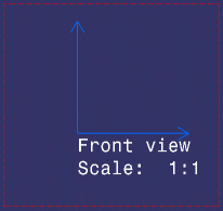
Creating 2D geometry |
|
-
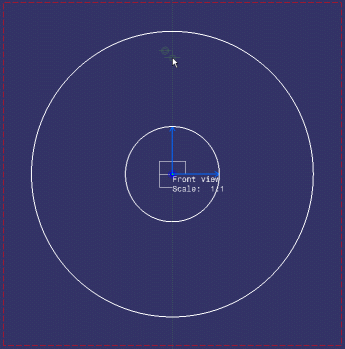
Click the Circle
 icon in the Geometry Creation toolbar. The Tools Palette
is automatically displayed.

-
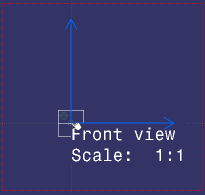
Click to select the front view origin as the circle center.
-
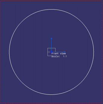
In the Tools Palette, type 90 as the radius value and press Enter.

You do not need to position the cursor in the Tools Palette, as already it has the focus. Simply start typing on your keyboard. The circle is created.
-
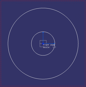
Repeat steps 1 to 3 to create a second circle, this time entering 30 as the radius value.
-
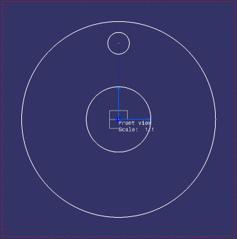
Repeat steps 1 to 3 to create a third circle, this time pointing to the absolute axis V direction so as to use it as the reference for the circle center, and entering 10 as the radius value.
Creating a center line with reference |
|
|
|
At this stage, you will be creating a center line with reference so as to show that there will be a hole pattern along it. |
-
Click Center Line with Reference
 in the Dress-up toolbar (Axis and Threads
sub-toolbar).
-
Select the circle to which the center line will be applied, that is the smallest circle (the last-created one).
-
Select the circle that will serve as the center line reference, that is the biggest circle (the first-created one).
The center lines are created and are associative with the reference circle.

-
Select the center lines. Manipulators appear.
-
Press the Ctrl key and drag the horizontal center line along the reference circle.
-
Click in the free space to validate.
The center line is extended along its reference circle.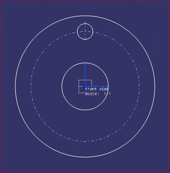
Creating dimensions |
|
|
|
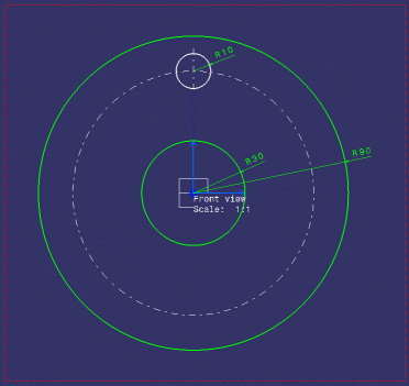
The dimensions that you will be creating in this task will be driving dimensions, as previously defined when configuring your options. |
-
Click Radius Dimensions
 in the Dimensioning toolbar (Dimensions
sub-toolbar).
in the Dimensioning toolbar (Dimensions
sub-toolbar).The Tools Palette is automatically displayed,
-
Make sure the Force dimension on element icon
 is active.
 -
Select a circle.
-
Click at the location where you want to position the dimension. The dimension is created.
-
Repeat steps 1 to 4 to create dimensions for the two other circles (the Force dimension on element icon remains active).
-
Re-position your dimensions if necessary.
-
Click Dimensions
 in the Dimensioning toolbar.
 -
Select the small and then the medium-size circles (or their center points) to create a distance dimension between their center points. The dimension is previewed.
-
If the previewed dimension value is not 70, type 70 as the distance value in the Tools Palette and press Enter.

The small circle will be moved accordingly.
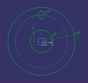
-
Click at the location where you want to position the dimension. The dimension is created.
-
Multi-select all dimensions using the Ctrl key.
-
Click Frame
 in the Text Properties
toolbar. The Frames sub-menu is displayed.
 -
Select the variable-size rectangle frame
 . Rectangle
frames are added to all dimensions. This shows that they are reference
dimensions.
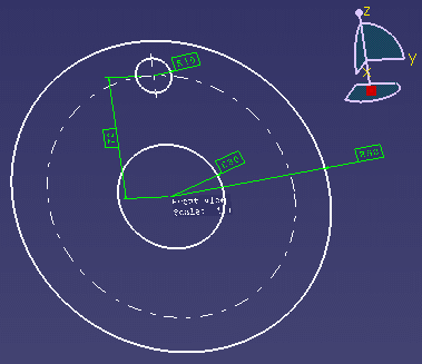 |
Now, let's complete the preliminary design of your part in another view.
![]()