This task shows you how to create a 3D plane.
-
Double-click the front view to activate it.
-
Click 3D Plane
 in the 3D Geometry toolbar (3D Outputs
sub-toolbar).


The Tools Palette appears.
-

-
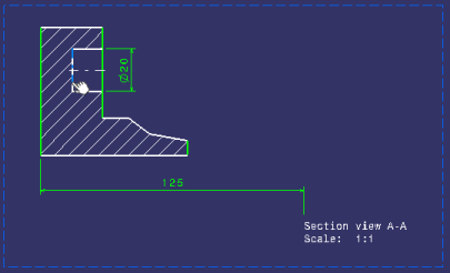
Select the line in the section view as shown below.

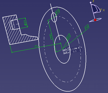
The 3D plane, Plane2DL.1, is created and it is listed in the specification tree, under the PartBody node.


- Of all elements created from 2D geometry in 2D Layout for 3D Design, only 3D profiles and 3D planes belong to the current part body.
- Note that 3D profiles and 3D planes are created under the current part body only when working in a hybrid design environment, that is when the Enable hybrid design inside part bodies and bodies option is selected in Tools > Options > Infrastructure > Part Infrastructure > Part Document tab (which is the case by default). Otherwise, when this option is not selected, 3D profiles and 3D planes are created in geometrical sets or ordered geometrical sets.
The 3D plane is also displayed in the 3D window.

![]()