B-axis and C-axis management capabilities are available only on a Turning operation belonging to a program assigned to a turret set as a 'Mill Turret'. A suitable machine must be referenced by the Part Operation: for example, a 'Mill Turret' can be specified on a multi-slide lathe machine.
A Tool Axis symbol on the Turning operation's Strategy tab page
![]() allows the B-axis orientation to be set and eliminates the
need for a tool change activity.
allows the B-axis orientation to be set and eliminates the
need for a tool change activity.

Tool axis is defined on turning operations linked to a mill turret (managing
a B-axis). Information that B-axis is managed on turret will be defined on the machine
Turret type will be defined as ‘mill turret’ on the NC machine.
No tool axis need to be defined on operations defined on a rotary turret.
Tool axis will be defined according to the Spindle axis system.
Note for multi spindle machine:
A Spindle axis system is defined on each Spindle.
Tool axis is defined on the main spindle axis.
Today, for all machining operations affected to the counter spindle, the tool path
computation is always done according to the main spindle axis system.
If capability to compute coordinates in the counter spindle is provided, the tool
axis of operation affected to the counter spindle will be defined in the counter
spindle axis system.
Tool axis is defined by geometry selection or manually (component values or angle
value)
Angle orientation is defined from the Radial axis to the Axial axis of the Spindle
axis system.
For operation defined on a mill turret (on which B axis is defined), the tool
is displayed according to the orientation defined by the tool axis.
The tool axis specified by the user will be displayed on the tool path replay panel
and is generated in the APT output.
For operation defined on another turret (not a mill turret), the tool axis is vector normal to the turning plane.
A BAXIS NC command is output at the beginning of an operation defined on a mill turret.
$$ OPERATION NAME : Rough Turning.1

	$$ Start generation of : Rough Turning.1

	$$

	FEDRAT/ 0.3000,IPR

	SPINDL/ 70.0000,RPM,CCLW

	BAXIS/1.000000, 0.000000, 0.000000

	GOTO / 58.63072, 0.00000, 136.34210

	GOTO / 58.63072, 0.00000, 134.34210

	FEDRAT/ 0.4000,IPR

	GOTO / 58.63072, 0.00000, 81.85882

	FEDRAT/ 0.8000,IPR

	GOTO / 58.84286, 0.00000, 82.07095
This syntax contains valuation of I,J,K coordinates of the operation tool axis (defining the B-axis orientation). Coordinates are defined in the machining axis (spindle axis).
Example: BAXIS/1,0,0
Turret axis orientation components (I,J,K) are generated in the output file (according to the 'Tool motion statement' option defined in NC Output option panel).
Note: TLAXIS syntax (that is output for a machine axis change) is not modified: coordinates of TLAXIS statement are the components of the vector normal to the turning plane.
For the following statements, the output depends on the 'Tool motion statement' option:
Tool motion statement = (X,Y,Z):
X, Y, Z
BAXIS/I,J,K
TLAXIS/Inormal, Jnormal, Knormal (components of the normal to the turning plane)
Tool motion statement = (X,Y,Z,I,J,K):
X, Y, Z, I, J, K
Tool motion statement = (X,Y,Z):
X, Y, Z
TLAXIS/Inormal, Jnormal, Knormal (components of the normal to the turning plane)
Tool motion statement = (X,Y,Z,I,J,K):
X,Y, Z,Inormal, Jnormal, Knormal
Inormal, Jnormal, Knormal are the components of the axis vector normal to the
turning plane
I, J, K are the components of the tool axis orientation vector that define the B
axis position.
Note: TLAXIS will not be output in the APT file for a Turning operation, unless an explicit Machine Axis Change is added by the user. An exception to this is when there is a change from Milling Operation to a Turning Operation. In this case, TLAXIS/ Inormal, Jnormal, Knormal will be output before the Turning Operation.
B axis move is simulated according to the tool axis defined on the turning operation.
Import of APT source file on which I,J,K coordinates are defined: tool axis is defined with the I,J,K coordinates.
Note: At Replay and Simulation, if tool axis is not correct (not in the turning plane) Radial axis is used for tool assembly orientation.
BAXIS syntax can be correctly interpreted by APT import functionality only when
the syntax is defined with a known order of parameters (the required parameters
of the syntax must respect the default syntax).
Tool path can be correctly replayed only when:
Major word and parameters must be set as follows:
BAXIS,/%MFG_MILL_TURRET_I_AXIS, %MFG_MILL_TURRET_J_AXIS, MFG_MILL_TURRET_K_AXIS
User changes the turret assigned to a Machining Program from one turret type to another type (for example, from Rotary to Mill Turret or vice versa). The Machining Operation will be marked as ‘not up to date’ in this scenario.
If you Cut, Copy and Paste a machining operation related to one Turret type to another Turret type (for example, from Rotary Turret to Mill Turret or inversely), the operation will have status Not up to date.
The C-axis inversion check box on the Turning operation's Strategy
tab page
![]() provides a C-axis rotation (0/180 degrees) without requiring a tool change activity.
provides a C-axis rotation (0/180 degrees) without requiring a tool change activity.
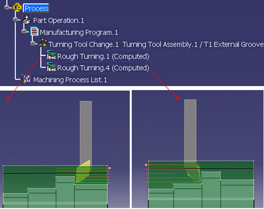
This allows machining of different areas (front and back areas of a part, or part on main spindle and part on a counter-spindle) using the same tool assembly. Only the tool orientation (inversion) differs when machining the different areas or parts.
The Tool path with B and C axis option is available in the Option tab of the Part Operation editor.
If you select this option, the generated tool path will take in to account the specified B-axis and C-axis values.
B-axis angle orientation is defined from the Spindle Radial axis to the Spindle Axial axis (see following figure for angle orientation). Setup angle is opposite to B-axis angle for a left hand tool and is in the same direction for a right hand tool with respect to a non-opposing upper turret. The following figure shows both the non-opposing and opposing cases and the corresponding Setup angle and B-axis angle conventions.

Behavior of the left hand tool with respect to the non-opposing turret case for setup and B-axis angle is shown in the figure below. This helps to interpret the tool position for different combinations of Setup angle, Tool Inversion, B-axis angle, and Tool Axis Flip (C axis) for a ZX direct axis machine for a non-opposing upper turret with respect to main spindle.

The tool path defined for a compensation point will be modified for different combinations of parameters (Setup angle, Tool Inversion, B-axis, and Tool axis flip). The effect of the tool path for a compensation point P1 is explained below.
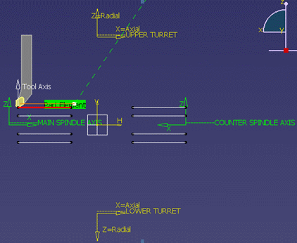
The effect of the B-axis and Tool axis flip (C-axis) on a Profile Finish turning operation defined on the main spindle using upper turret is shown in the figure below. The tool path is generated with respect to the P1 compensation point.
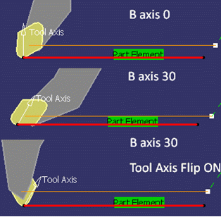
When the Tool path with B and C axis option is selected, the tool path includes an offset corresponding to the specified B-axis angle.
Consider the tool path generated for the P1 compensation point.
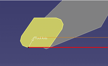
The figure below shows tool displayed for a B-axis angle 30 degrees, when the Tool path with B and C axis option is not selected.
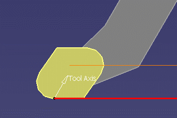
The example below shows an APT source output in this case:
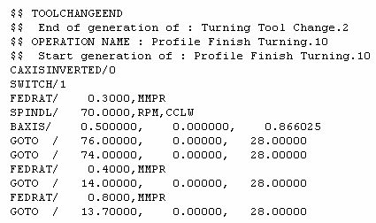
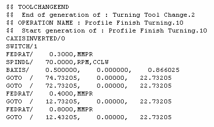
When the Tool path with B and C axis option is selected, there is an offset in the tool path but the tool display will not change.
The example below shows an APT source output in this case:
With this enhancement you cannot use the APT source code of tool paths which have B and C axis. You have to regenerate them.