Click
![]() ,
then select the
geometry to be machined
,
then select the
geometry to be machined
![]() .
.
More information can be found in
Selecting Geometry.
Select the machining strategy tab
![]() and choose a
guiding strategy for this operation:
and choose a
guiding strategy for this operation:
- Between contours where the tool sweeps between guide contours,
- Parallel contours where the tool sweeps out an area by following contours parallel to a reference contour,
- Spine contour where the tool sweeps across a contour in perpendicular planes.
Depending on the chosen strategy, select the necessary guiding elements.
Then set the following strategy parameters according to the desired machining:
Specify the tool
![]() to be used,
feeds
and speeds
to be used,
feeds
and speeds ![]() ,
and NC macros
,
and NC macros
![]() as needed.
as needed.
Multi-Axis Contour Driven: Strategy Parameters
Multi-Axis Contour Driven: Machining Parameters
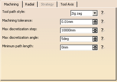
Tool path style
Indicates the cutting mode of the operation:
- Zig Zag: the machining direction is reversed from one path to the next
- One way: the same machining direction is used from one path to the next.
Machining tolerance
Specifies the maximum allowed distance between the theoretical and computed
tool path.
Maximum discretization step
Ensures linearity between points that are far apart.
Maximum discretization angle
Specifies the maximum angular change of tool axis between tool
positions.
It is used to add more tool positions (points and axis) if value is
exceeded.
Minimum path length
Specifies the minimum length that a path needs to have to be taken into
account.
- The Maximum discretization step and Maximum discretization angle influence the number of points on the tool path.
- The values should be chosen carefully if you want to avoid having a high concentration of points along the tool trajectory.
- These parameters also apply to macro paths that are defined in
machining feedrate.
They do not apply to macro paths that do not have machining feedrate (RAPID, Approach, Retract, User, and so on). - Default value for Maximum discretization step is 100 m. Default value for Maximum discretization angle is 180 degrees.
Multi-Axis Contour Driven: Strategy Parameters

Offset on contour
Distance the tool will be from the guide contour at the beginning of the
operation
Maximum width to machine
Specifies the width to machine starting from the guide contour in the
stepover direction.
Stepover side
Defines
the side of the contour where machining will be performed (left or right),
i.e. if you choose Left, the tool will machine on the left side of the guide
contour for the Maximum width distance,
- From contour: machining starts from the guide contour (in red in the
figure below)
over an area defined by the maximum width to machine.
- To contour: machining is done up to the guide contour (in red in the
figure below)
over an area defined by the maximum width to machine.
The limit of the area to machine is indicated in yellow in the figures above.
Multi-Axis Contour Driven: Radial Parameters

Radial strategy mode

Defines how the distance between two consecutive paths is to be computed.
Scallop height:
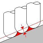
The associated parameter is Scallop height
that
specifies the maximum scallop height between
two consecutive tool paths in a radial strategy.
Note that the machining tolerance influences the distance between two
consecutive paths.
When the machining tolerance value is increased, the distance between two
consecutive paths is decreased according to the specified maximum scallop
height value.
Distance on part:
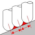
The associated parameter is Distance between paths
that defines the maximum distance between
two consecutive tool paths in a radial strategy.
Distance on plane:
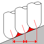
The associated parameter is Distance between paths
that defines the maximum distance between
two consecutive tool paths in a radial strategy.
Number of paths:
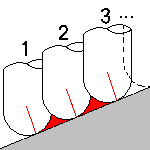
The associated parameter is Number of paths
that
defines the number of tool paths in a radial strategy.
The following offsets and positional modifiers allow you to extend or reduce the area to machine in the Between Contours guiding strategy without needing to create additional geometry.
Offset on guide 1
Specifies an offset on the first guide contour in Between Contours guiding
strategy.
Offset on guide 2
Specifies an offset on the second guide contour in Between Contours guiding
strategy.
Position on guide 1
Specifies the position of the tool with respect to the first guide contour:
Inside, Outside or On.
Position on guide 2
Specifies the position of the tool with respect to the second guide contour:
Inside, Outside or On.
Same offset on
stops
When an offset is set on guides, you can
choose to apply the same
offset on stops
by selecting this check box.
Multi-Axis Contour Driven: Tool Axis Parameters
Below you will find the explanations of the various Guidance types and
tool axis modes,
then the explanations of the associated parameters.
Note that modifications of the tool axis generated by the mode you have selected apply only to the machining passes, not to the between paths passes.
(Only Tool Axis Parameters tabs containing parameters have been captured).

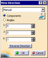
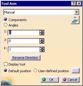
You can define several axes with this icon:
- V, for the view direction,
- A, for the tool axis direction.
The view directions defines the machining guiding plane: machining is done in planes parallel to the guiding plane.
The view direction defines the accessible areas for the tool. These areas are accessible if the angle between the view direction and the normal to surface is less than 85 degrees.
The tool axis definition depends on the Tool axis mode. The tool axis
arrow turns white when its definition box is not available
(e.g. when the tool axis is defined through a point or a line, ...).
Clicking one of the direction arrows displays its definition box.
- View direction:
- Tool axis direction:
Tool axis mode

Lead and Tilt


In this mode the tool axis is normal to the part surface with respect to
a given lead angle in the forward tool motion
and with respect to a given tilt angle in the perpendicular direction to
this forward motion.
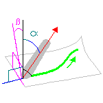
Guidance
Specifies how the tool axis is to be guided.
There are several types of lead and tilt modes as follows:
- Fixed lead and tilt: Here both the lead and tilt angles are
constant.
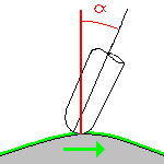
- Variable lead and fixed tilt: Here the tool axis is allowed
to move from the specified lead angle within a specified range,
the tilt angle remaining constant.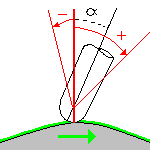
- Fixed lead and variable tilt: Here the tool axis is allowed
to move from the specified tilt angle within a specified range,
the lead angle remaining constant.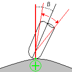

The tool axis remains constant for the operation.
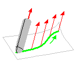
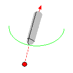
Thru a Point

The tool axis passes through a specified point.
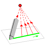
The tool axis can be oriented to point To
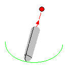
or From the point.
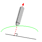
Normal to Line

The tool axis passes through a specified curve, and is normal to this
curve at all points.
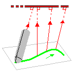
The tool axis can be oriented to point To
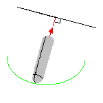
or From the line.
Optimized Lead

The tool axis is allowed to vary from the specified lead angle within an
allowed range.
The allowed range is defined by Minimum and Maximum lead angles.
The back of the cutter is to be kept clear of the part by means of a Minimum
heel distance.
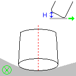
Optimized lead works as follows:
- lead defined as minimum to fit the part curvature
- lead increases if necessary to respect the Minimum heel distance.
If the required lead is outside the allowed range, the tool position will
not be kept in the tool path.
The maximum material removal is obtained when the tool curvature along
the trajectory matches the part curvature.
4-axis Lead/Lag

The tool axis is normal to the part surface with respect to a given lead
angle in
the forward direction and is constrained to a specified plane.
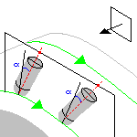
The tool axis is computed like in Lead and Tilt mode and then projected
into the constraint plane.
Lead angle
Specifies a
user-defined incline of the tool axis in a plane defined by the direction of
motion and
the normal to the part surface. The lead angle is with respect to the part
surface normal.
Maximum lead angle
Specifies a maximum lead angle.
Minimum lead angle
Specifies a minimum lead angle.
Tilt angle
Specifies a
user-defined incline of the tool axis in a plane normal to the direction of
motion.
The tilt angle is with respect to the part surface normal.
Allowed tilt
Specifies
the range of allowed tilt variation.
Minimum heel distance
Allows the back of the cutter to be kept clear of the part
(for example, when machining a smooth concave ruled part with Optimized Lead
tool axis guidance).

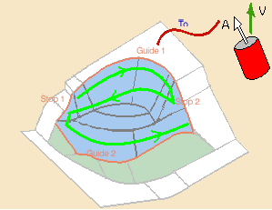

This strategy is used mainly to machine revolute surfaces, e.g. hub machining, deep pockets, ...
The tool orientation is controlled by a geometrical curve (guide), that must be continuous.
An open guide can be extrapolated at its extremities.
Click the red curve in the sensitive icon and select a curve in the 3D viewer.
The tool can be oriented From or To the guide.
Mode

Defines how the position of the tool is computed:
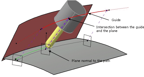
- Normal to the path: for a given contact point, the
intersection of the plane normal to the path with the guide give the tilt
angle of tool. If several intersection are found, the nearest one is taken
into account.
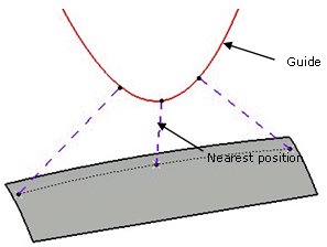
- Nearest position: the tool is oriented by the point that
gives the shortest distance between the guide and the contact point.
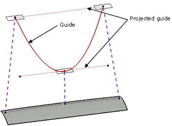
- Nearest position along view direction: the guide is
projected on a plane normal to the view direction.
The tool is oriented by the point that give the shortest distance between the projected guide and the current contact point.
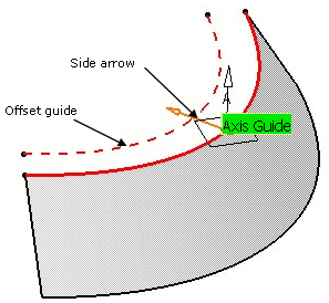
Offset on guide
You can define an
offset on the guide. The offset is computed on a plane defined by the
tangent of the guide and the view direction.
Click the Axis Guide arrow to define on which side the offset is
applied.
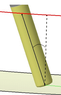
Specifies an angle in the forward direction, between the default tool axis and the actual tool axis:
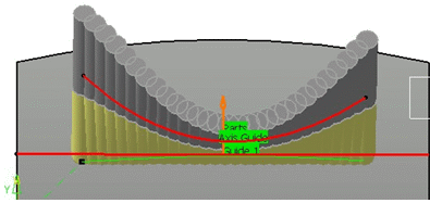
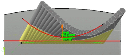
Note
that depending on the Lead angle, the tool axis will not remain on the
tilting guide:
Example:
Lead angle=0
Lead angle=20
Extend guide
Select this check box to
extrapolate the extremities of an open guide.

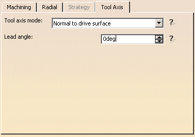
Use the red surface in the graphic icon to select the drive surface.
We recommend that you use a smooth surface.
Lead angle
Specifies an angle in the forward direction, between the default
tool axis and the actual tool axis:

Multi-Axis Contour Driven: Cutter Compensation Parameters
(Double-click the part operation and push the Machine icon to open the
Machine Editor)
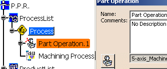
In the Machine Editor, the Compensation tab contains options for:
- globally defining the 3D contact cutter compensation mode: None/Contact/Tip and Contact
- imposing the compensation mode to all operations supporting the
selected mode
whatever the choice defined at machining operation level.
If the options are set as follows, compensation can be managed at
machining operation level.

In this case a Compensation tab appears in the Strategy page of the
machining operation editor,
and the following options are available.
Output type
Allows you
to manage the generation of Cutter compensation (CUTCOM) instructions in the
NC data output:
The following options are proposed:
3D Contact (G29/CAT3Dxx)
The tool contact point will be visualized during tool path replay.
Cutter compensation instructions are automatically generated in the NC data
output.
An approach macro must be defined to allow the compensation to be applied.
Example of generated APT source:
$$ Start generation of : Multi-Axis Contour Driven.1

      FEDRAT/ 1000.0000,MMPM

      SPINDL/ 70.0000,RPM,CLW

      CUTCOM/NORMPS

      $$ START CUTCOM NORMPS XC, YC, ZC, XN, YN, ZN, I, J, K

      .../...

      CUTCOM/OFF

      $$ END CUTCOM NORMPS XC, YC, ZC, XN, YN, ZN, I, J, K

      $$ End of generation of : Multi-Axis Contour Driven.1
None
Cutter compensation instructions are not automatically generated in the
NC data output.
However, CUTCOM instructions can be inserted manually.
For more information, please refer to How to generate CUTCOM syntaxes
provided in the Prismatic Machining User's Guide.
Multi-Axis Contour Driven: Geometry

You can specify the following Geometry:
- Part with possible Offset on Part.
- For Between Contours strategy, the area to machine on the selected
part is determined
by selecting two guide curves and two limit curves. Tool paths are parallel to the selected guide curves. - For Parallel Contours strategy, the area to machine on the selected
part is determined
by selecting a guide curve specifying a maximum width to machine. Tool paths are parallel to the spine curve. - For Spine Contour strategy, the area to machine on the selected part
is determined by selecting a spine curve.
Tool paths are perpendicular to the spine curve.
- For Between Contours strategy, the area to machine on the selected
part is determined
- The thickness of the offset can be negative.
- If you want to use a negative value, the tool corner radius must be greater than the absolute value of the offset.
- Check elements with possible Offset on Check.
- Areas to avoid.
- Limiting Contour with possible
offset.

The area to machine is defined by the projection of the limiting contour on the part along the view direction.
The value of Offset can be positive, to extend the area to machine (up to the part boundaries),

or negative to reduce the area to machine.
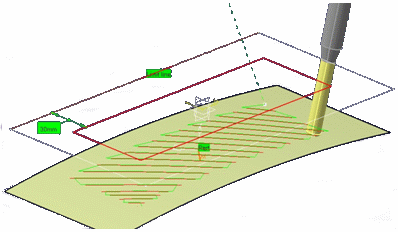
The Limiting Contour re-limits the contact path (in red above) and not the tool tip path (in green above).
Side to machine lets you define which portion of the part you want to machine (Inside or Outside of the limiting contour).
Stop position lets you decide where the tool stop with respect to the limiting contour (Inside, Outside, On).
Stop mode specifies which part of the tool is considered at the stop position (Contact point or Tool end)
You can use Offset Groups and Features when defining geometry.
Multi-Axis Contour Driven: Tools
Recommended tools for Multi-Axis Contour Driven are End Mills, Face Mills, Conical Mills and T-Slotters.
Multi-Axis Contour Driven: Feeds and Speeds
In the Feeds and Speeds tab page, you can specify feedrates for approach,
retract and
machining as well as a machining spindle speed.
Feedrates and spindle speed can be defined in linear or angular units.
A Spindle output checkbox is available for managing output the SPINDL
instruction in the generated NC data file.
If the checkbox is selected, the instruction is generated. Otherwise, it is
not generated.
Feeds and speeds of the operation can be updated automatically according to tooling data and the Rough or Finish quality of the operation. This is described in Update of Feeds and Speeds on Machining Operation.
Multi-Axis Contour Driven:Macros
General information about macros can be found in
NC Macros.
Information about the operating mode can be found in
Defining Macros.
Information about Surface Machining macro parameters can be found in
Macro Parameters.

