in your Machining program.
More information about the operating mode is available in Create a Multi-Axis Tube Machining Operation.
Click
![]() and select the
geometry to be machined
and select the
geometry to be machined
![]() .
.
More information can be found in
Selecting Geometry.
Select the machining strategy tab
![]() and choose a guiding strategy for this operation:
and choose a guiding strategy for this operation:
Then set the following strategy parameters according to the desired machining:
Specify the tool
![]() to be used, feeds and speeds
to be used, feeds and speeds ![]() ,
and NC macros
,
and NC macros
![]() as needed.
as needed.
Multi-Axis Tube Machining: Strategy Parameters
Multi-Axis Tube Machining: Guiding Strategy
Three guiding strategies are available:
- Around guide,
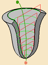
that lets you choose between two tool path styles, Zig zag or One way,
- Along guide,
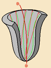
that lets you choose between three tool path styles: Zig zag, One way, or Back and forth.
You must then select a guide:
- either by clicking the curve in the sensitive icon and selecting one in the 3D Viewer,
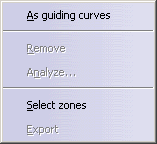
- or by right-clicking the curve in the sensitive icon and selecting
As guiding axis,
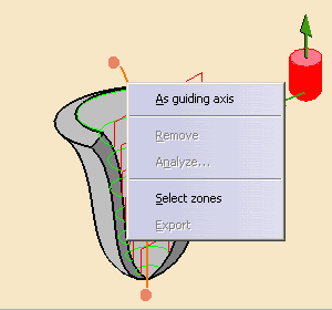
Another sensitive icon is displayed.
Click the red point and the arrow to select one point and an axis direction:
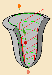

When this icon is displayed, the contextual menu changes to bring you back to the other selection mode.
- the machining direction is then displayed at one end of the guide.
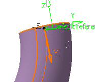
Click this arrow to invert the machining direction if necessary.
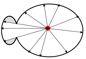
Areas that cannot be reached by the beams issued from the guide are not machined:
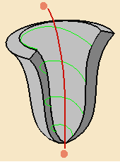
In the pictures below, the guide is represented in red.
 represents
areas that are not machined.
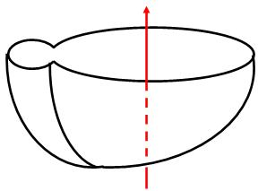
View normal to the guide
- you can select limiting points by clicking the end
points of the curve or the axis in the sensitive icon.

You can: - click the limiting point in the sensitive icon and select a point in the 3D viewer,
- or right-click the limiting point in the sensitive icon and
select On guide in the contextual menu.
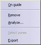
A red dot appears on the Guide. You can drag it to the required position.

Click the vertical arrow to define the tool axis.
Click the horizontal arrow to define the start direction, i.e.:
- the beginning of each pass if the Guiding strategy is set to Around guide,
- or the beginning of the helix if the Guiding strategy is
set to Helical.
Multi-Axis Tube Machining: Machining Parameters
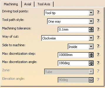
Driving tool points

Specifies how the tool path is computed:
- Tool tip. This mode requires a ball end tool. It improves the quality of the tool path and usually does not require Collision Checking.
- Contact on part. This mode often requires that you activate Collision Checking. It is more time consuming than Tool tip.
Tool path style
Available when Guiding strategy is set to Around guide
or Along Guide.
Indicates the cutting mode of the operation:
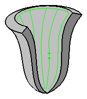
- Zig Zag: the machining direction is reversed from one path
to the next
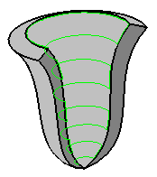
- One way: the same machining direction is used from one path
to the next.
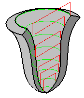
- Back and forth: available when Guiding strategy
is set to Along guide. Each pass is covered twice, first in the
machining direction, then back.
Machining tolerance
Specifies the maximum allowed distance between the theoretical and computed
tool path.
Way of cut
Specifies the direction of cut:
- Clockwise or
- Counterclockwise.
Side to
machine
Specifies on which side of the part you want to perform the machining:
- Inside or
- Outside.
Maximum discretization step
Ensures linearity between points that are far apart.
Maximum discretization angle
Specifies the maximum angular change of tool axis between tool
positions.
It is used to add more tool positions (points and axis) if value is
exceeded.
- The Maximum discretization step and Maximum discretization angle influence the number of points on the tool path.
- The values should be chosen carefully if you want to avoid having a high concentration of points along the tool trajectory.
- These parameters also apply to macro paths that are defined in
machining feedrate.
They do not apply to macro paths that do not have machining feedrate (RAPID, Approach, Retract, User, and so on). - Default value for Maximum discretization step is 100 m. Default value for Maximum discretization angle is 180 degrees.
Available when Driving tool points is set to Tool tip.

Specifies which zone is machined:
- Tube: machines the tube. Recommended when the part has non adjacent faces. You must select a guide.
- Cavity: machines the cavity, i.e. the bottom of the tube.
The tool path is computed by projecting the tool on the part from a point and along a direction defined by the user.
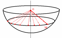
You can select a point and a direction. The side of projection is that of the tool axis.
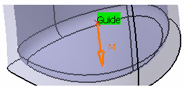
or a curve. The point of projection is the extremity of the curve pointed by the tool axis, the direction of projection is the tangent of the curve at this point.
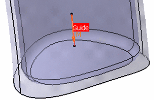
- Tube and cavity: machines the tube and its bottom in one
shot.
Inside the part, tube is machined first, outside the part, cavity is machined first.
You must select a guide.

Required when Zone is set to Cavity. It sets the
end angle of the cavity.
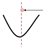
- In Cavity or Tube and cavity modes, if the selected guide is infinite (axis) you must select a limiting point to machine the cavity.
- This limiting point is always inside the cavity (even if the machining side is Outside).
- In Cavity mode, machining does not work properly when the guide crosses
the part. In this case, you must select a limiting point above the part
(as shown by the arrow).
Multi-Axis Tube Machining: Axial Parameters
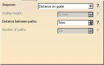
Stepover

Defines how the distance between two consecutive paths is to be computed.
Scallop height:
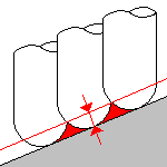
The associated parameter is Scallop height
that
specifies the maximum scallop height between two consecutive tool paths in a
radial strategy.
Distance on part:
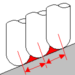
The associated parameter is Distance between paths
that defines the maximum distance between two consecutive tool paths in a
radial strategy.
Distance on guide:
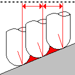
The associated parameter is Distance between paths
that defines the maximum distance between two consecutive tool paths in a
radial strategy.
Number of paths:
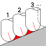
The associated parameter is Number of paths
that
defines the number of tool paths in a radial strategy.
Multi-Axis Tube Machining: Tool Axis Parameters
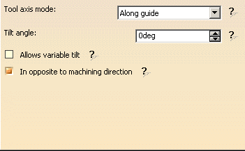

Below you will find the explanations of the tool axis modes,
then the explanations of the associated parameters.
Note that modifications of the tool axis generated by the mode you have selected apply only to the machining passes, not to the between paths passes.
Fixed Axis
The tool axis remains constant for the operation.
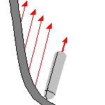
There are no associated parameters.
Thru a Point
The tool axis passes through a specified point.

There are no associated parameters.
You must define the point using the sensitive icon:
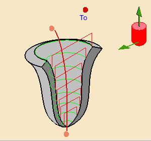
The tool axis can be oriented to point To or From the
point (click the label to switch from one status to the other).
Along guide
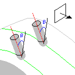
The tool axis makes a constant Tilt angle with the guide.
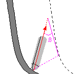
You must define this Tilt angle.

By default, the Allows variable tilt check box is not selected.
If you select it, the tool axis is automatically adjusted around its initial
position to avoid collision with part or checks.
By default, the In opposite to machining direction check box is
selected.
This check box enables you to decide whether the tool is in the machining
direction or in the opposite direction.
Lead and Tilt
In this mode the tool axis is normal to the part surface with respect to
a given lead angle in the forward tool motion
and with respect to a given tilt angle in the perpendicular direction to
this forward motion.
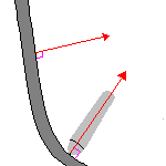
The associated parameters depend on the Guidance selected.
Guidance
Specifies how the tool axis is to be guided.
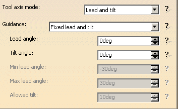
There are several types of lead and tilt modes as follows:
|
|
The purpose of the variable modes is to avoid collisions between the part to machine and the tool. |
- Fixed lead and tilt:
Here both the lead and tilt angles are constant.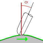
- Variable lead and fixed tilt:
Here the tool axis is allowed to move from the specified lead angle within a specified range, the tilt angle remaining constant.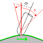
- Fixed lead and variable tilt:
Here the tool axis is allowed to move from the specified tilt angle within a specified range, the lead angle remaining constant.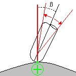
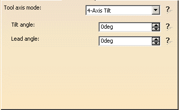
4-Axis Tilt
The tool axis is normal to the part surface with respect to
a given tilt angle and is constrained to a specified plane.
You must enter the Tilt angle and the Lead angle:
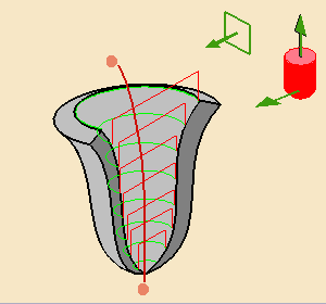
and define the constraining plane using the sensitive icon:
Multi-Axis Tube Machining: Geometry
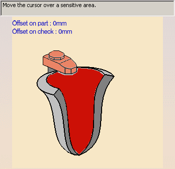
You can specify the following Geometry:
- Part with possible Offset on Part.
- The thickness of the offset can be negative.
- If you want to use a negative value, the tool corner radius must be greater than the absolute value of the offset.
- Check elements with possible Offset on Check.
Geometrical zones are supported.
Collision Checking is also available.
Multi-Axis Tube Machining: Tools
Recommended tools families for Multi-Axis Tube Machining are:
- face mill,
- end mill (ball-ended or not),
- conical mil (ball-ended or not),
- T-slotter.
Multi-Axis Tube Machining: Feeds and Speeds
In the Feeds and Speeds tab page, you can specify feedrates for approach,
retract and
machining as well as a machining spindle speed.
Feedrates and spindle speed can be defined in linear or angular units.
A Spindle output checkbox is available for managing output the SPINDL
instruction in the generated NC data file.
If the checkbox is selected, the instruction is generated. Otherwise, it is
not generated.
Feeds and speeds of the operation can be updated automatically according to tooling data and the Rough or Finish quality of the operation. This is described in Update of Feeds and Speeds on Machining Operation.
Multi-Axis Tube Machining: Macros
General information about macros can be found in
NC Macros.
Information about the operating mode can be found in
Defining Macros.
Information about Surface Machining macro parameters can be found in
Macro Parameters.
Add normal motion helps avoiding collisions in the linking macros.
Add Circular motion is very useful return in a level macros, when the
Guiding strategy is set to Along guide.
