 |
This procedure describes how to create a machine
instruction activity. A machine instruction activity is not created
within NC Machine Tool Simulation; rather, it is created in one of the V5
machining workbenches and used by the NC Machine Tool Simulation
workbench.
The role of a machine instruction activity is to allow a parallel or
peripheral axis machine to be used in a simulation. You can lock
one of the parallel axes and specify the other axes that can move freely.
|
 |
Before creating a machine instruction, open the
Process1.CATProcess file within
any V5 machining workbench. Assign the
ParallelAxisMachineSample.CATProduct to the Part Operation. |
 |
-
On the PPR tree, select Machine Program.1,
and click Machine Instruction  in the Auxiliary Operation toolbar.
 |
The Machine Instruction command appears on the Auxiliary
Operation toolbar only if you have a license for NC Machine Tool
Simulation as well as a V5 machining workbench. |
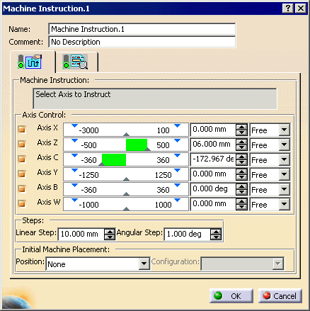
The Machine Instruction dialog box
appears with the Properties
 tab on
top. tab on
top. |
 |
Machine Instruction activities on
Turrets and Spindles
-
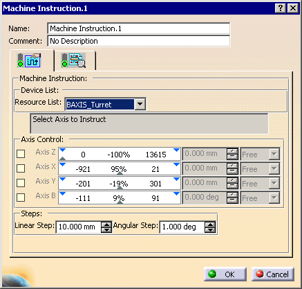
Launch the machine
instruction activity in mill-turn context, the Resource List combo box in the
Machine Instruction
dialog lists all the devices available, such as, Turrets and
Spindles.
-
Select the particular Turret on which the machine
instruction activity has to be created.
-
On selection, the Axis Control box shows the list of DOFs (Degree of freedom
of a joint in a machine) in the Turret. you can now move
the Turret to any particular location by selecting the
appropriate DOFs.
Note that Locking a turret is not possible.
-
-
-
-
|
 |
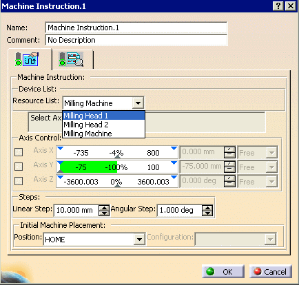
When the dialog box first appears, none of the axes are
selected. If you enter a subsequent machine instruction, the dialog
box opens with the axis set as they were for the previous machine
instruction activity. |
-
Select the axis to lock.
| Once selected, the axis remains locked during the simulation
until another machine instruction is encountered. |
-
Select one or more axes to move freely.
-
(Optional) Enter a comment in the
Comment box.
-
Select a Position for Initial Machine
Placement.
Possible positions are:
- List of machine home positions
- Previous Machine Instruction (if defined)
- Last point of previous machine operation
- First point of next machine operation
|
-
Select a Configuration (if available).
| If one or more configurations is available for the machine
position, you can select a configuration. |
-
Click OK.
| The machine instruction activity is added to the
PPR tree. |
 |
 |
If a generated transition path appears after the machine
instruction is inserted, click Update Transition Path .
Otherwise, the machine instruction data is not taken into account
in the transition path. .
Otherwise, the machine instruction data is not taken into account
in the transition path. |
|
 |
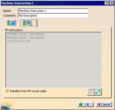
The Syntax
 tab shows the
following instructions: tab shows the
following instructions: |
| |
 |
|
|
For rotary axes, the direction of rotation
generated in the syntax is based on the NC Machine axes
directions and follows this convention:
- Counter Clockwise rotation is generated if the
machine has to move along its positive direction i.e.
from a lower value to a higher value.
- Clockwise rotation is generated if the machine has
to move from a higher to a lower value.
|
| |
The contextual commands available, when you select the
Machine Instruction object, are: |
| |
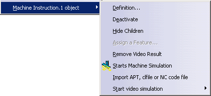 |
| |
Tool Path Replay is not available because no
tool path is created. |
| |
Each machine instruction activity is specific to a
machine. If a new machine is assigned to the Part Operation, the change
of machine does not generate a warning. After a machine change, if you
edit the machine instruction activity, you receive warning messages about
compatibility issues, should any apply. |
| |
The Machine Instruction activity can be used to index
spindles to specified values, for Mill-turn machines.
The spindle to be instructed can be selected from the Device List
combo. Once the spindle is chosen, you can modify the DOF values of the
spindle, as necessary, and can lock / unlock as needed. |


