![]()
This procedure describes how to set or modify existing workpiece and tool mount points on the machine, and how to mount the workpiece automatically. Although workpiece and tool mount points are generally set when machines are created in the NC Machine Tool Builder workbench, you can also set them in NC Machine Tool Simulation.
In the context of older milling machines (created till Release 18), you can modify workpiece and tool mount points using the NC Controller functionality. For new machines, this functionality is completely replaced by the Modify Mount Point command.
The Modify Mount Point command cannot be used in the context of older milling machines.
To follow this procedure, you must first select and assign a machine to a part operation.
-
Select a Resource to open the Mount Point Management dialog box.
On the top of this dialog box is the Mount Point Type drop-down box, which contains the following options:
-
Tool Mount Points
-
WorkPiece Mount Points
-
Head Mount Points - It is the point defined on the milling machine, where the interchangeable head is to be mounted. The Head Mount Point must be defined if you want to use interchangeable milling heads in the milling machine.
The Tool Mount Points option is selected by default.
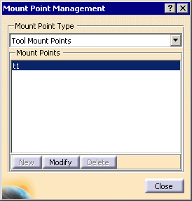
-
-
Select one of the mount points from the Mount Points text-selection box.
Selecting any item in the list will highlight the corresponding representation in the 3D viewer.
-
Click Modify and Edit the mount point name in Station Name dialog box, if required.
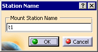
The compass snaps to the currently defined mount point.
-
Place the compass appropriately.
-
In the 3D window or PPR tree, select the part on which this mount point is to be associated, and click OK in the Set Location dialog box that appears.
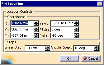
Set or Modify the Workpiece Mount Point under the NC Controller
-
In the PPR tree, double click on the Workpiece Mount Point node.
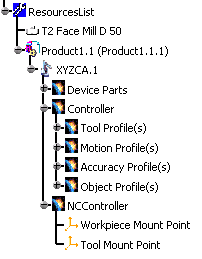
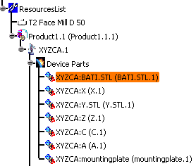
On the geometry, a compass appears showing the current location of the workpiece mount point. The part associated with that mount point appears highlighted on the PPR tree. 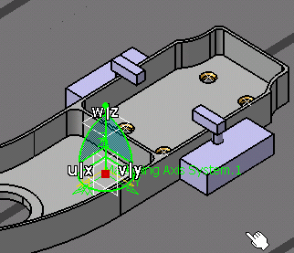
-
In the 3D window or the PPR tree, select a mount part.

The mount part you select can be the same part highlighted on the PPR tree. The Set Location dialog box appears. 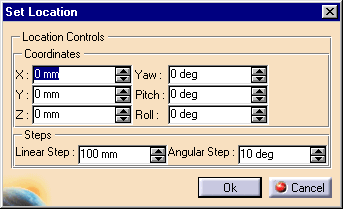
-
Define the location using one of these methods:
- In the dialog box, enter the desired values to edit the axes coordinates and steps.
- Manipulate the compass to alter the mount point's location (when you move the compass, the values within the Set Location dialog box change accordingly).
- Select a tag point as the location.

When you select a tag, the compass jumps to the tag point. The values within the Set Location dialog box become those the location and orientation of the tag.
-
Click OK.
Mount the Workpiece

In the context of this scenario, the Machine Axis System is set up (you can verify that this is done by observing whether the axis labeled, as is the case in the image, above), and the Workpiece Mount point has been selected (see Steps 1-4, above). Before using the Workpiece Automatic Mount  command in your normal work, verify that these two steps have been
taken.
Workpiece Automatic Mount  does the following::
- Positions the workpiece (i.e., the command snaps the workpiece to the workpiece mount point).
- Creates an attachment object (i.e., the machine is defined as the parent; the workpiece is defined as the child). Once you establish an attachment between two items, the child item moves relative to the parent item. An attachment object can be right-clicked on the geometry, and deleted, if so desired.
- Transforms all machining-operation- and tool-path-related information to the right location. Once Workpiece Automatic Mount is performed, either a tool path replay or machine simulation occurs at the right location.
-
On the Positioning Tools toolbar, click Workpiece Automatic Mount
 .
.The attachment between the machine (Product1.1.1) and the workpiece (Product1.1) appears on the geometry. 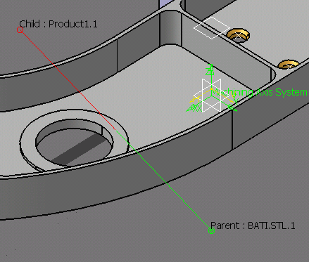
Mounting w.r.t user-selected MAS
In the case of Milling Machines, instead of auto mounting the workpiece using the Part Operation Machining Axis System, you can select the workpiece from the Product list, and also the Machining Axis System. Then the workpiece will be mounted on the milling machine bed with respect to the selected axis system.
In the case of Mill-Turn Machines, instead of mounting the workpiece with respect to the spindle axis system, you can select the desired axis system. The workpiece will then be mounted on the spindle, with respect to the selected axis system.
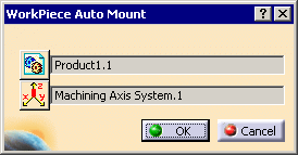
In the case of Milling machines and Single-spindle Mill-turn machines, you can select the NC Assembly and also the Machining Axis System as shown below::
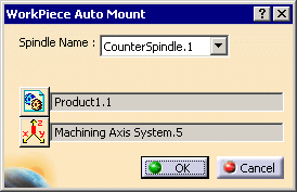
In the case of Multi-spindle Mill-turn machines, you can select the Machining Axis in addition to the Spindle, and the NC Assembly.
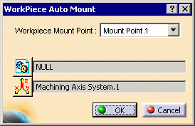
In the case of Milling machines with multiple workpiece mount points, you can select the Workpiece Mount Point from the combo-box, in addition to the NC Assembly and the Machining Axis System.
Set or Modify the Tool Mount Pointt
-
In the PPR tree, double-click on the Tool Mount Point node.

A compass appears showing the current location of the tool mount point. 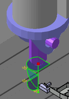
-
Repeat Steps 2 and 3, above.